14 Intel Desktop Board D865GBF/D865GLC Quick Reference
8. Connecting Internal Headers
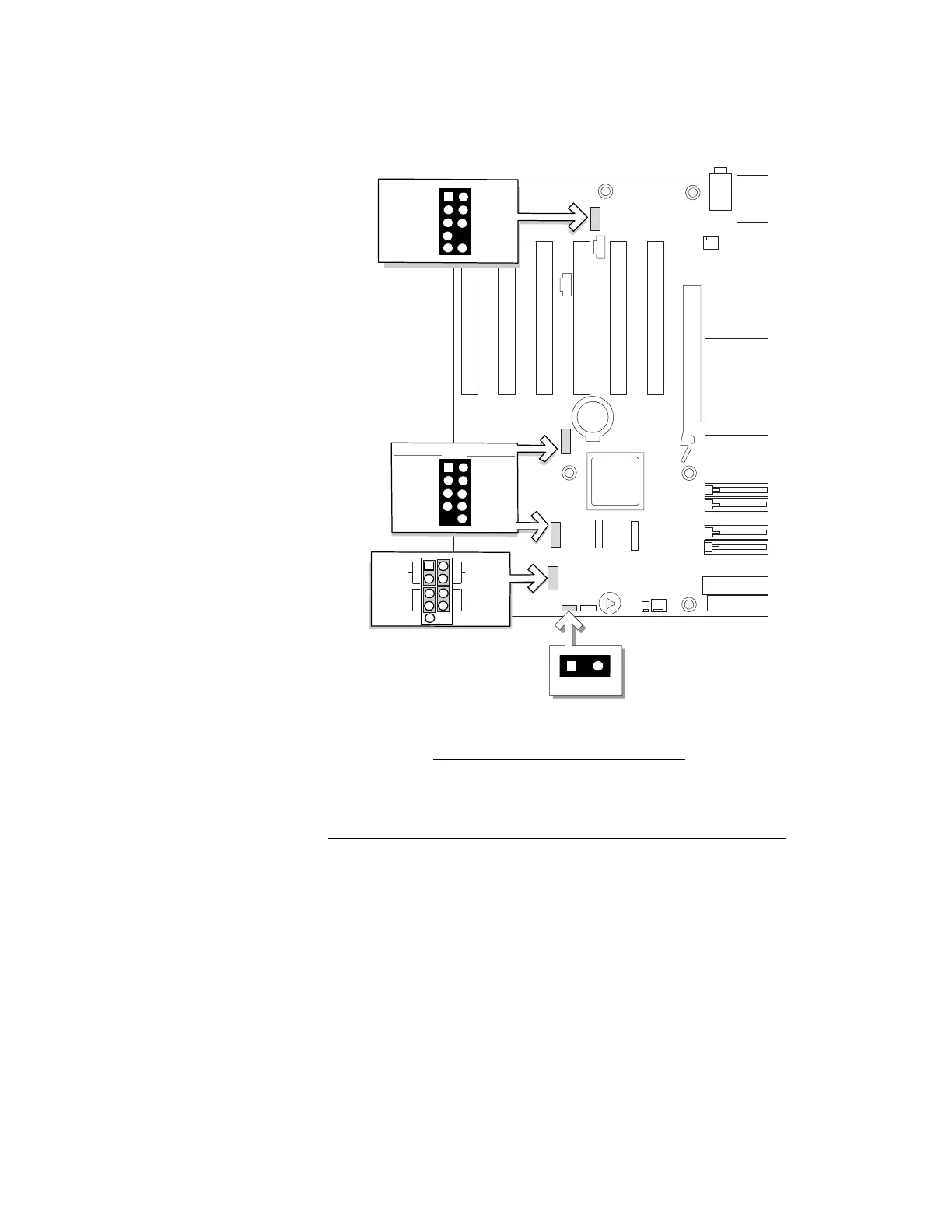
Figure 8 shows the location of internal headers. Observe the precautions in
“Before You Begin” on page 3 before installing cables.
OM15250
A
D
J9H1
J9J1
J9F1
1
J9A2
2
C
1
5
6
7
9
3
4
2
10
AUD-MIC
AUD-GND
AUD-VCC
AUD-RET-R
AUD-RET-L
AUD-FPOUT-L
HP-ON
AUD-FPOUT-R
AUD-MIC-BIAS
Key
B
1
5
6
7
8
3
4
2
10
Power (
+5 V
)
Ground
Ground
Power (
+5 V
)
D-
D-
D+D+
N/C
Key (
no pin
)
USB A
USB B
Reset
On/Off
Power LED
HD LED
1
3
5
7
8
6
4
2
9
J9J3
Label Description
A Front panel audio header
B USB 2.0 headers
C Front panel header
D Power LED header
Figure 8. Internal Headers
 Loading...