Technical Reference
51
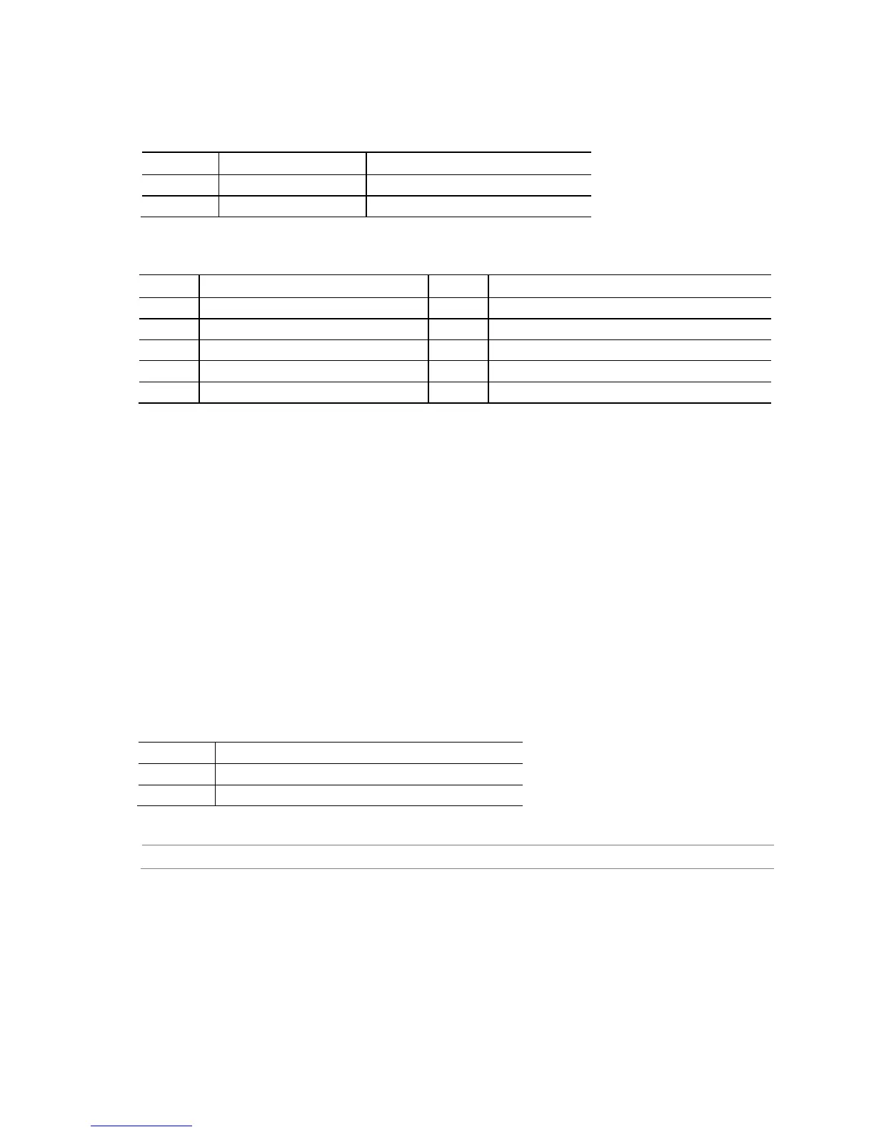
Table 24. Backlight-off and Mute Header
Pin Signal Name Description
1 BKLT_OFF Backlight-off and mute signal
2 GND Ground
Table 25. System ID / Custom Solutions Header
Pin Signal Name Pin Signal Name
1 Prog_LED 2 Ground
3 Key (no pin) 4 SMB_CLK
7 PWRBTN# 8 HDM CEC
9 +5 VSB 10 SCI/SMI GPI
2.2.2.2 Add-in Card Connectors
The board has a PCI Express Half-Mini Card slot.
2.2.2.3 Power Supply Connectors
The board has the following power supply connectors:
• External Power Supply – the board can be powered through a 19 V DC
connector on the back panel. The back panel DC connector is compatible with a
7.4 mm/OD (outer diameter) and 5.1 mm/ID (inner diameter) plug, where the
inner contact is +19 (±10%) V DC and the shell is GND. The maximum current
rating is 12 A.
• Internal Power Supply – the board can alternatively be powered via the internal
19 V DC 1 x 2 power connector, where pin 1 is GND and pin 2 is +19 (±10%) VDC.
The maximum current rating for this connector is 9 A.
Table 26. Internal Power Supply Connector Pinout
Pin Signal Name
1 Ground
2 DC input: +8 (±10%) through +19 (±10%) VDC
For information about Refer to
Power supply considerations Section 2.6.1, page 60
 Loading...