Intel Desktop Board DP67BG Product Guide
48
S/PDIF Header
Figure 24, A shows the location of the S/PDIF output header. Table 6 shows the pin
assignments and signal names for the S/PDIF connector.
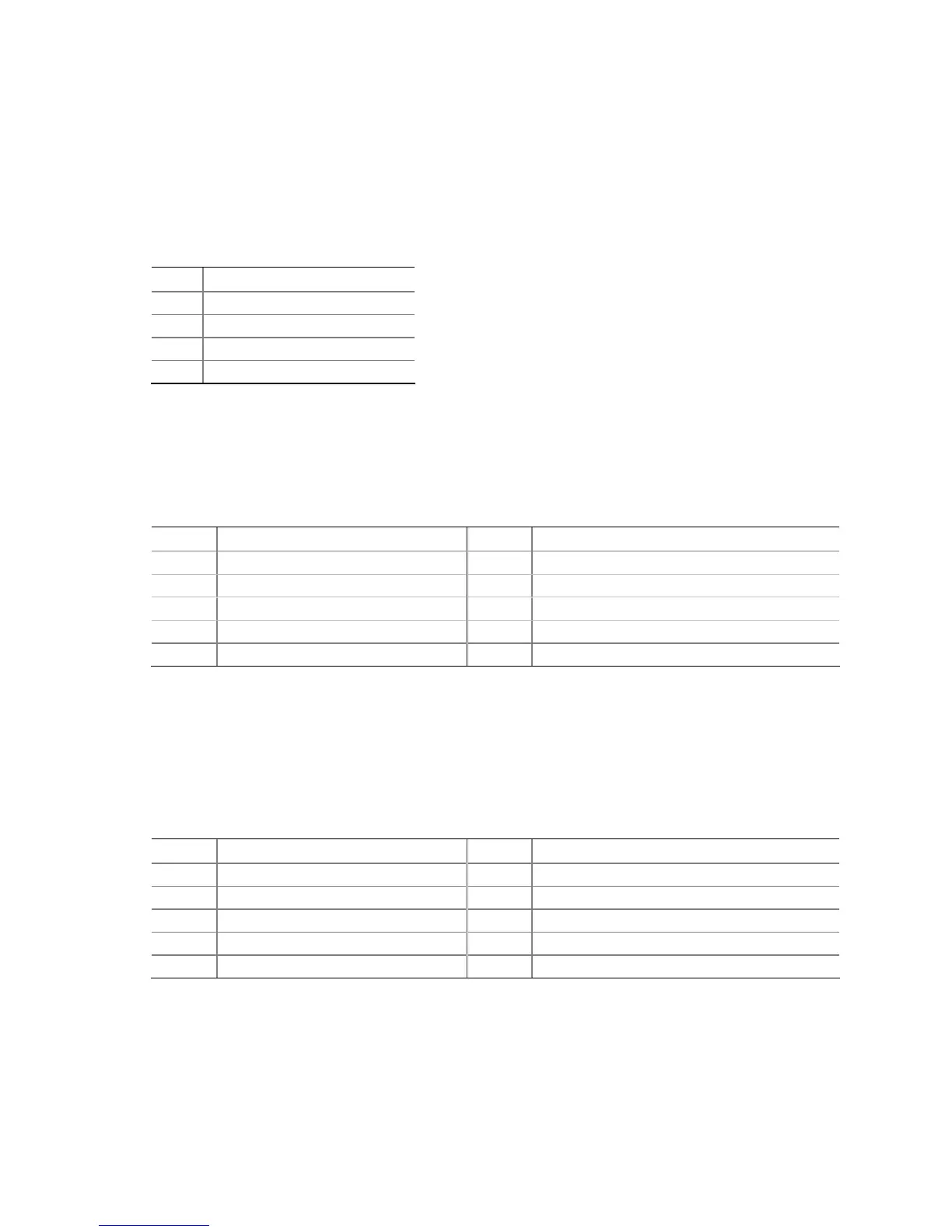
Table 6. S/PDIF Header Signal Names
Pin Description
1 Ground
2 S/PDIF Out
3 Key (no pin)
4 +5 VDC
IEEE 1394a Header
Figure 24, B shows the location of the IEEE 1394a header. Table 7 shows the pin
assignments and signal names for the IEEE 1394a header.
Table 7. IEEE 1394a Header Signal Names
Pin Signal Name Pin Signal Name
1 TPA1+ 2 TPA1-
3 Ground 4 Ground
5 TPA2+ 6 TPA2-
7 +12 V 8 +12 V
9 Key (no pin) 10 Ground
Front Panel Intel HD Audio Header
Figure 24, C shows the location of the front panel Intel HD Audio header. Table 8
shows the pin assignments and signal names for the front panel Intel HD Audio
header.
Table 8. Front Panel Intel HD Audio Header Signal Names
Pin Signal Name Pin Signal Name
1 PORT 1L 2 GND
3 PORT 1R 4 PRESENCE#
5 PORT 2R 6 SENSE1_RETURN
7 SENSE_SEND 8 KEY (no pin)
9 PORT 2L 10 SENSE2_RETURN
 Loading...