Intel Desktop Board DP67BG Product Guide
50
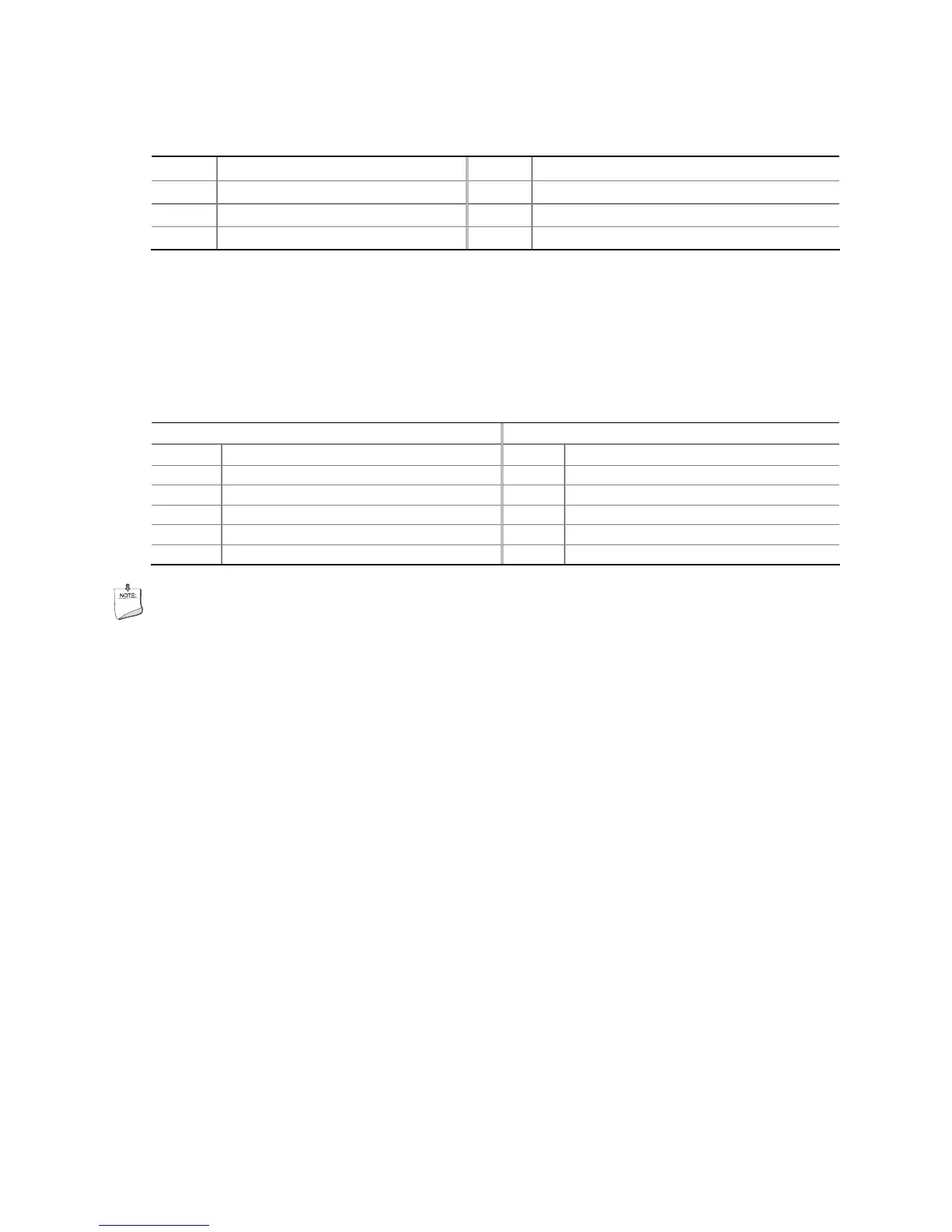
Table 11. Back Panel CIR Header Emitter (Output) Header Signal Names
Pin Signal Name Pin Signal Name
1 Emitter Out 1 2 Emitter Out 2
3 Ground 4 Key (no pin)
5 Jack Detect 1 6 Jack Detect 2
USB 2.0 Headers
Figure 24, G shows the location of the USB 2.0 headers. Table 12 shows the pin
assignments and signal names for each USB 2.0 header. Each USB header can be
used to connect two USB devices.
Table 12. USB 2.0 Header Signal Names
USB Port A USB Port B
Pin Signal Name Pin Signal Name
1 Power (+5 V) 2 Power (+5 V)
3 D- 4 D-
5 D+ 6 D+
7 Ground 8 Ground
9 Key 10 No Connection
NOTE
Computer systems that have an unshielded cable attached to a USB port might not
meet FCC Class B requirements, even if no device or a low-speed USB device is
attached to the cable. Use a shielded cable that meets the requirements for a
full-speed USB device.
 Loading...