Packaging Technology
R
Intel
®
E7500/E7505 Chipset MCH Thermal Design Guide 11
2 Packaging Technology
The E7500 chipset consists of three individual components: Intel
®
E7500 chipset MCH, Intel
®
82870P2 P64H2, and Intel
®
82801CA ICH3-S. The E7505 chipset includes the same components
except for the I/O controller hub, which is an Intel
®
82801DB ICH4. The E7500/E7505 chipset
MCH components use a 42.5 mm, 6-layer FC-BGA package (see Figure 2 and Figure 3). For
information on the P64H2 package, refer to the Intel
®
82870P2 PCI/PCI-X 64-bit Hub 2 (P64H2)
Thermal and Mechanical Design Guidelines and the Intel
®
82870P2 PCI/PCI-X 64-bit Hub 2
(P64H2) Datasheet. For information on the ICH3-S package, refer to the Intel
®
82801CA I/O
Controller Hub 3 (ICH3-S) Datasheet. For information on the ICH4 package, refer to the Intel
®
82801DB I/O Controller Hub 4 (ICH4) Datasheet.
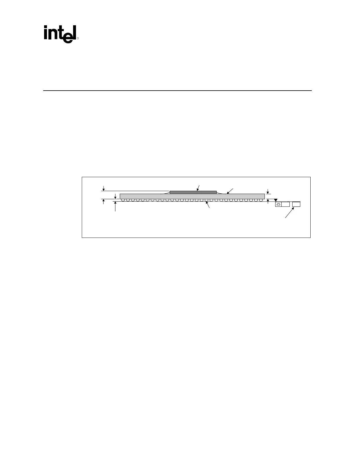
Figure 2. MCH Package Dimensions (Side View)
1.10 ± 0.10 mm
Die
Substrate
0.60 ± 0.10 mm
Seating Plane
Package_Dimensions_Side
1.940 ± 0.150 mm
0.20
–C–
See note 1.
NOTES:
1. Primary datum –C– and seating plane are defined by the spherical crowns of the solder balls.
2. All dimensions and tolerances conform to ANSI Y14.5M–1982.

 Loading...