Advisor Advanced ATSx500A User Guide 3
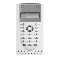
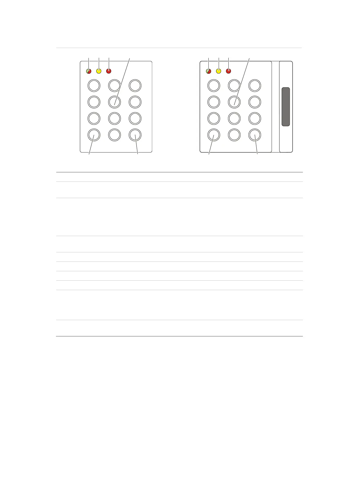
Figure 6: ATS1151/ATS1156 readers
On: area set
Flashing: general alert (EN 50131)
Green on: AC mains supply on.
Green flashing: AC mains supply off, or unlocked while unset.
Red on: all areas set. See also “Access control indication note”
below.
Red flashing: unlocked while set.
On: All zones are in normal state
Flashing: general alert (EN 50131)
Keys 0 to 9, numerical data
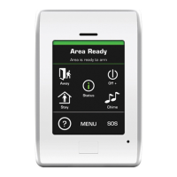
Green on: System is disarmed
Green flashing: Door open time
Green / red flashing: Valid card presented
Red (ATS125x): System is armed
ATS4000: System is not ready
ATS125x: Always on
Access control indication note
Access control keypads and readers, which are connected to door controllers
instead of the control panel, indicate areas in a different way:
• Dual LED is lit red when any associated area is set.
• Area 1 LED is on when any associated area is set. Area LEDs 2 to 16 are not
used.
1 2 3
4 5 6
7 8 9
*
0 #
(4) (5) (6)
(7) (8)
(3)
1 2 3
4 5 6
7 8 9
*
0 #
(3) (4) (5) (6)
(7) (8)
 Loading...