• The LTE Module draws a maximum of 30 mA average during normal operation. In PowerSave Mode, during or
immediately following an AC power failure, the module will draw only 10 mA on average.
• Avoid mounting the panel in areas with excessive metal or electrical wiring, such as furnace or utility rooms.
• Leave 12 to 18 inches of open space around the module antenna.
• Do not install the control panel and module in a basement or other below-ground location. Doing so will negatively
impact LTE signal strength.
Tools and supplies needed
The following tools and supplies are required:
• Small flat-head and Phillips screwdrivers
• Screws (included)
• Antenna (included)
Module insertion and antenna installation
Before installing the module, disconnect the battery and AC power from the panel.
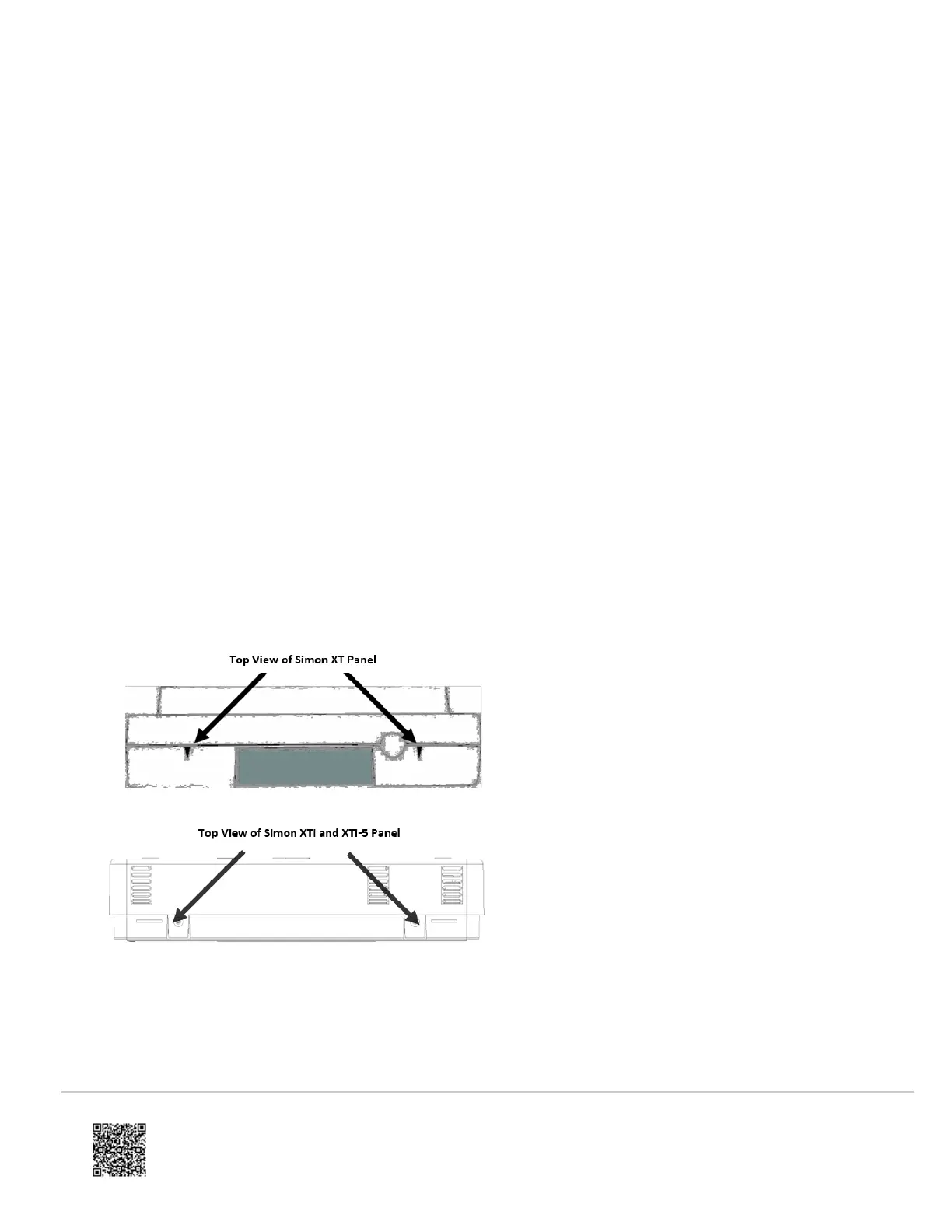
1. Open the panel by pressing the two tabs on the top of the XT or by lifting the tabs on the XTi and XTi-5 panel, as
shown in Figure 1.
Figure 1: Top View of Simon XT, XTi, and XTi-5 panels
2. The module compartment can be found behind the front panel that swings down, to the left of the battery
compartment as seen in Figure 2.
Figure 2: Module compartment for Simon XT, XTi, and XTi-5 panel
https://answers.alarm.com/ADC/Partner/Installation_and_Troubleshooting/Panels/Interlogix_Simon_XT/Interlogix_Simon_XT_…
Updated: Tue, 31 Mar 2020 20:51:49 GMT
3
 Loading...