6 / 64 P/N 145797999-2 • REV B • ISS 19MAR12
24
25
ST400
CP
26
SB01
EN: Installation Manual
Introduction
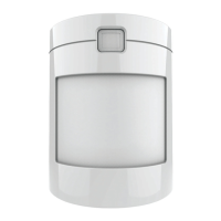
The VE735 and VE736 are PIR motion sensors.
They have a patented verified PIR technology.
Installation guidelines
The technology in this detector resists false alarm
hazards. Nevertheless avoid potential causes of
instability, such as:
• Direct sunlight on the detector
• Heat sources within a field of view
• Strong draughts onto the detector
• Large animals in a field of view
• Obscuring the detector’s field of view with large
objects, such as furniture
Install the detector so that the expected movement
of an intruder will be across the fields of view (see
example in Figure 21, item 1). This is the direction
best detected by PIR detectors.
Mounting the detector
1. Lift off the custom insert and remove the
enclosed screw (Figure 1).
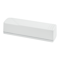
2. Using a screwdriver, carefully prise open the
detector (Figure 2).
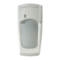
3. Remove the interior part (Figure 3).
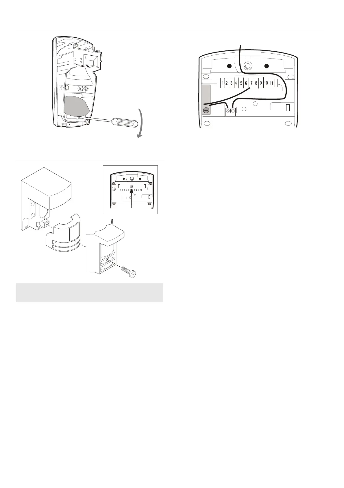
4. Fix the base to the wall between 1.8 m and 3.0
m (5.9 to 9.8 ft.) from the floor. For flat
mounting, use a minimum of two screws (DIN
7998), at least one in position A and one in
position B. For corner mounting, use screws in
positions C or D (see Figures 4 and 5).
Note: Not all screw positions have pry-off
tamper. Non pry-off positions are shown in the
warning box.
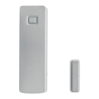
5. Wire the detector. See Figures 7 and 8.
Note: All wiring must be provided according to
National Electrical Code, NFPA 70 and CSA
C22.1, Canadian Electrical Code, Part I, Safety
Standard for Electrical Installations.
Figure 16 shows a single detector wiring,
Figure 17 — multiple devices connection.
6. Select the desired jumper and DIP switch
settings (see “Setting the detector” on page 7).
7.
Replace the interior part (Figure 9).
 Loading...