EasyManuals Logo
Home>INVT>DC Drives>GD20-0R7G-4-EU

INVT GD20-0R7G-4-EU User Manual

INVT GD20-0R7G-4-EU
168 pages
To Next Page IconTo Next Page
To Previous Page IconTo Previous Page
Page #131 background imageLoading...
Page #131 background image
Goodrive20-EU series VFD Communication protocol
127
written is determined by the command "data number", the max. number of continuous writing
is 16 words.
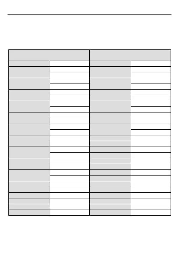
For instance: Write 5000 (1388H) to 0004H of the VFD whose slave address is 02H, write 50
(0032H) to 0005H of the VFD whose slave address is 02H, then the structure of this frame is
listed as below:
ASCII master command message (the
command sent by the master to VFD)
ASCII slave response message (the
message sent by the VFD to master)
START
':'
START
':'
ADDR
'0'
ADDR
'0'
'2'
'2'
CMD
'1'
CMD
'1'
'0'
'0'
High bit of starting
address
'0'
High bit of starting
address
'0'
'0'
'0'
Low bit of starting
address
'0'
Low bit of starting
address
'0'
'4'
'4'
High bit of data number
'0'
High bit of data number
'0'
'0'
'0'
Low bit of data number
'0'
Low bit of data number
'0'
'2'
'2'
Byte number
'0'
LRC CHK Hi
'E'
'4'
LRC CHK Lo
'8'
High bit of data 0004H
content
'1'
END Hi
CR
'3'
END Lo
LF
Low bit of data 0004H
content
'8'
'8'
High bit of data 0005H
content
'0'
'0'
Low bit of data 0005H
content
'3'
'2'
LRC CHK Hi
'1'
LRC CHK Lo
'7'
END Hi
CR
END Lo
LF
7.4 Definition of data address
The address definition of the communication data in this part is to control the running of the
VFD and get the state information and relative function parameters of the VFD.

Table of Contents

Questions and Answers:

Question and Answer IconNeed help?

Do you have a question about the INVT GD20-0R7G-4-EU and is the answer not in the manual?

INVT GD20-0R7G-4-EU Specifications

General IconGeneral
BrandINVT
ModelGD20-0R7G-4-EU
CategoryDC Drives
LanguageEnglish

Related product manuals