EasyManuals Logo
Home>INVT>DC Drives>Goodrive100-PV Series

INVT Goodrive100-PV Series User Manual

INVT Goodrive100-PV Series
89 pages
To Next Page IconTo Next Page
To Previous Page IconTo Previous Page
Page #12 background imageLoading...
Page #12 background image
Goodrive100-PV Series Solar Pumping VFD Installation guidelines
10
Well
S2
S3
COM
GD100-PV
VFD
High water level switch
Low water level switch
Common terminal
Water
tower
S1
S4
COM
Forced switch to mains
1PH/2PH algorithm
shifting
Common terminal
(+) (-)
Q1
PV input
U V W
Water
pump
Figure 3-3 Standard wiring diagram
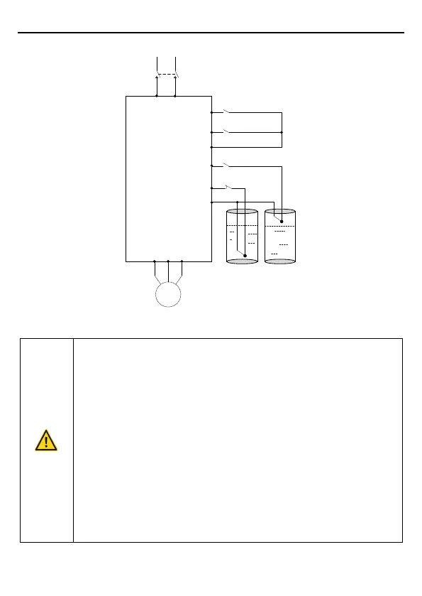
The DC breaker Q1 must be installed as the protection switch for PV input.
In parallel connection, the combination box special for PV must be used.
When the distance between the PV input component and VFD exceeds 10
meters, type-II surge protection devices must be configured at the DC
side.
When the distance between the pump and VFD exceeds 50 meters, it is
recommended to configure output reactors. See appendix A.4 for the
output reactor model selection.
The VFD automatically runs after being powered on. If parameters need to
be set, follow the parameter setting instructions in chapter 5.
Before connecting the braking resistor cable, remove the yellow labels of
PB, (+), and (-) from the terminal blocks. Otherwise, poor connection may
occur.

Questions and Answers:

Question and Answer IconNeed help?

Do you have a question about the INVT Goodrive100-PV Series and is the answer not in the manual?

INVT Goodrive100-PV Series Specifications

General IconGeneral
BrandINVT
ModelGoodrive100-PV Series
CategoryDC Drives
LanguageEnglish

Related product manuals