Goodrive100-PV Series Solar Pumping VFD Power frequency & PV switching solution
79
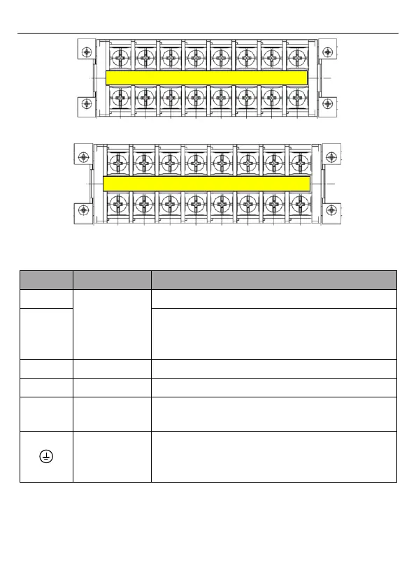
Figure C-4 Wiring terminals of -4 models for VFDs ≤2.2kW
Figure C-5 Wiring terminals of -S2/-SS2 models for VFDs ≤2.2kW
Wiring terminal functions
3PH 380/220V AC input terminals, connected to the grid
Neutral wire. For 4-37kW models, use 3PH 4-wire
distribution system and connect the neutral wire to
terminal N.
1PH 220V AC input terminals, connected to the grid
Solar cell panel input terminals
3PH/1PH AC output terminals, connected to pump motor
Note: 1PH motors must connect to terminals U and W.
Safety grounding terminal. Each VFD must be grounded
properly.
Note: It is at the bottom of the chassis.
C.4 Parameter setting method
Connect the external PV voltage detection signal to the HDI terminal (auto switching by
default). Ensure that the PV voltage detection threshold is 300V for the -4 models and it is
200V for the -2/-S2/-SS2 models. After the correct connection, set P15.32 to 0.
 Loading...

