Goodrive100-PV Series Solar Pumping VFD Installation guidelines
12
U1
U2
V2
V1
L1
L2
C1
C2
W
U
V
U1
U2
V2
V1
L1
L2
L
N
K
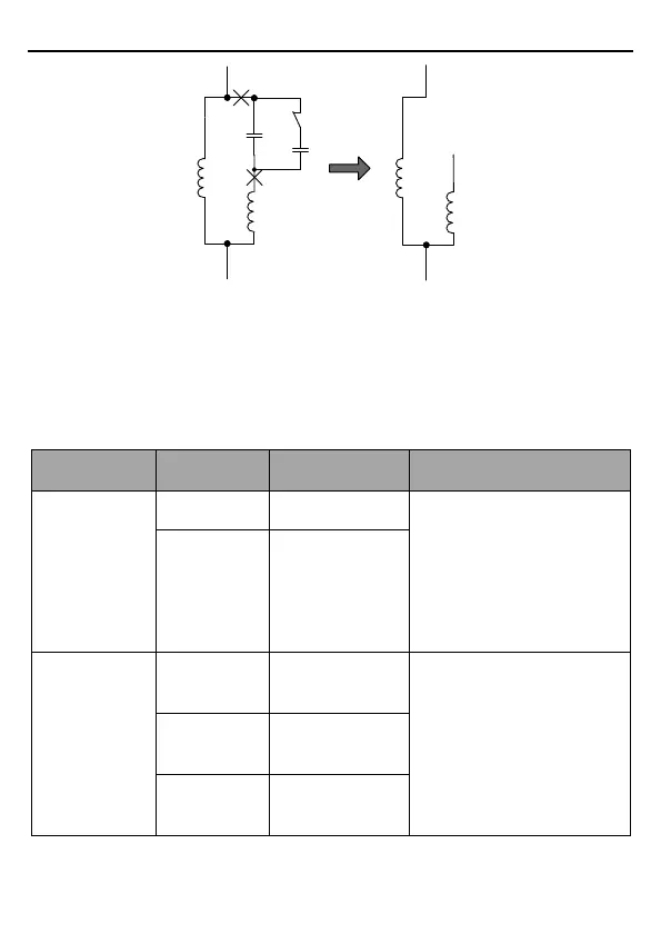
U1 and V1 are the common terminals of the windings. Connect them to the output terminal W
of the solar pumping VFD. Connect U2 to the output terminal U of the VFD. Connect V2 to the
output terminal V of the VFD. (Note: Use the screws equipped with the VFD.) Connect S4 of
the VFD to COM in short circuited manner.
3.2.2 Terminals of control circuit
Functions of control terminals
It provides the power of
24V±10% and maximum
current of 200mA.
It functions as the working
power supply of digital input
and output or externally
connects to the sensor power
supply.
Forced switch to
power frequency
Terminal feature parameters:
1. Internal impedance: 3.3kΩ
2. Acceptable voltage input:
12–24V
3. Maximum input frequency:
1kHz
S1: Forcible switch to power
frequency (Switching-on
indicates switching to power
 Loading...

