Goodrive20-EU series VFD Communication protocol
119
In ladder logic, CKSM calculated the CRC value according to the frame with the table inquiry.
The method is advanced with easy program and quick calculation speed. But the ROM space
the program occupied is huge. So use it with caution according to the program required space.
7.2.3 ASCII mode
Communication protocol belongs to hexadecimal system. The meaning of message
character in ASCII: "0"…"9", "A"…"F", each hex is represented by the ASCII
message corresponds to the character.
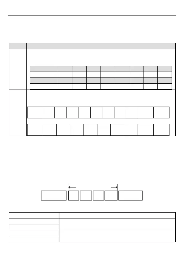
Starting bit, 7/8 data bit, check bit and stop bit. The data formats are listed as
below:
11-bit character frame:
In ASCII mode, the frame header is ":" ("0*3A"), frame end is "CRLF" ("0*0D" "0*0A") by
default. In ASCII mode, all the data bytes, except for the frame header and frame end, are
transmitted in ASCII code mode, in which four high bit groups will be sent out first and then,
four low bit groups will be sent out. In ASCII mode, the data length is 8 bit. As for 'A' – 'F', its
capital letters is adopted for ASCII code. The data now adopts LRC checkout which covers
slave address to data information. The checksum equals to the complement of the character
sum of all the participated checkout data.
ASCII data frame format
Modbus message
Starting character:
“0x3A”
Slave
address
Function
code
Data
Checkout
Ending character:
“0*0D”“0*0A”
Standard structure of ASCII frame:
Communication address:
8-bit address is formed by the combination of two ASCII codes
Function code:
8-bit address is formed by the combination of two ASCII codes

 Loading...


