Goodrive20-EU series VFD Installation guide
17
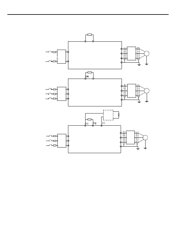
3.2 Standard wiring
3.2.1 Connection diagram of main circuit
Braking unit
Braking resistor
PB
(+)
Output
reactor
Output
filter
Braking resistor
PB
Output
reactor
Output
filter
Braking resistor
Input
reactor
Input
filter
Braking resistor
Input
reactor
Input
filter
Input
reactor
Input
filter
Three-phase 380V≤2.2kW
Three-phase 220V≤0.75kW
Three-phase 380V≥4kW
Three-phase 220V≥1.5kW
DC+
DC-
Output
reactor
Output
filter
Single-phase
200V~240V
50/60Hz
Three-phase
200V~240V
50/60Hz
Three-phase
380V~480V
50/60Hz
Three-phase
200V~240V
50/60Hz
Three-phase
380V~480V
50/60Hz
Fuse
Fuse
Fuse
L
N
U
v
w
PE
R
S
T
U
v
w
PE
R
S
T
U
v
w
PE
M
M
M
Figure 3-3 Connection diagram of main circuit
Note:
The fuse, brake resistor, input reactor, input filter, output reactor, output filter are
optional parts. Please refer to Peripheral Optional Parts for detailed information.
Remove the yellow warning labels of PB, (+) and (-) on the terminals before connecting
the brake resistor; otherwise, poor connection may be occur.
 Loading...


