Goodrive20-EU series VFD Product overview
12
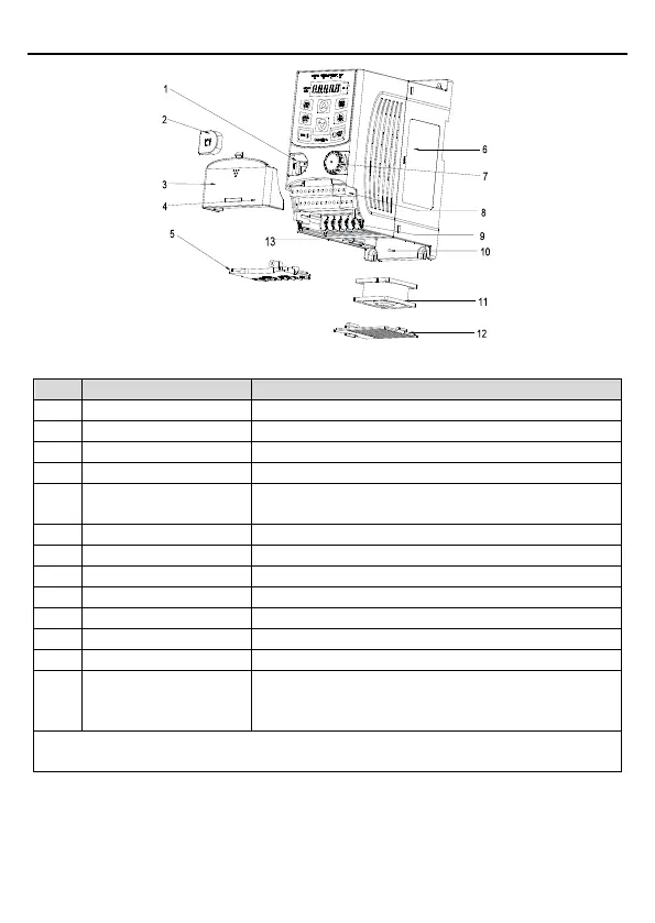
Figure 2-3 Product structure (3PH 400V, ≤2.2kW)
Description
Connect the external keypad
Protect the external keypad port
Protect the internal parts and components
Hole for the sliding cover
Protect the inner components and fix the cables of the
main circuit
See section 2.5 "Name plate" for details.
Refer to chapter 4 "Keypad operation procedure".
See chapter 3 "Installation guide" for details.
See chapter 3 "Installation guide" for details.
Fix the fan cover and fan.
See chapter 6 "Fault tracking" for details.
The same as the bar code on the name plate
Note: The bar code is on the middle shell which is under
the cover.
Note: In above figure, the screws at 4 and 10 are provided with packaging and specific
installation depends on the requirements of customers.
Below is the layout figure of the VFD (Three phase 400V, ≥4kW) (take the VFD of 4kW as the
example).
 Loading...


