Goodrive20-EU series VFD Installation guide
20
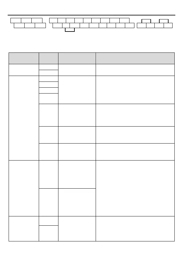
S1 S2 S3 S4 HDI Y1 AI2 AI3
+24V PW COM COM GND AO1 AO2 485+
RO1A RO1B RO1C
RO2A RO2B RO2C
+10V
485- +24V H1 +24V H2
Figure 3-11 Connection terminal diagram for VFDs ≥ 4kW
485 communication interface
1. Internal impedance: 3.3kΩ
2. 12 – 30V voltage input is available
3. The terminal is the dual-direction input
terminal
4. Max. input frequency: 1kHz
High frequency
input channel
Except for S1 – S4, this terminal can be
used as high frequency input channel.
Max. input frequency: 50kHz
Duty cycle: 30% – 70%
The working power of digital input is
provided by an external power supply.
Power range: 12 V–30 V
1. Contact capacity: 50mA/30V;
2. Output frequency range: 0 – 1kHz;
3. Default is STO state output indicator.
1. Safe torque stop (STO) redundant input,
externally connected to NC contact, STO
acts when the contact is open, and the
drive stops output;
2. The safe input signal cable should be
shield cable within 25m.
3. When employing STO function, please
disassemble the short circuit plate on the
terminals shown in fig 3.10 and fig 3.11.
External 24V±10% power supply and the
maximum output current is 200mA。
Generally used as the operation power
supply of digital input and output or external
sensor power supply
 Loading...


