Basic Operation
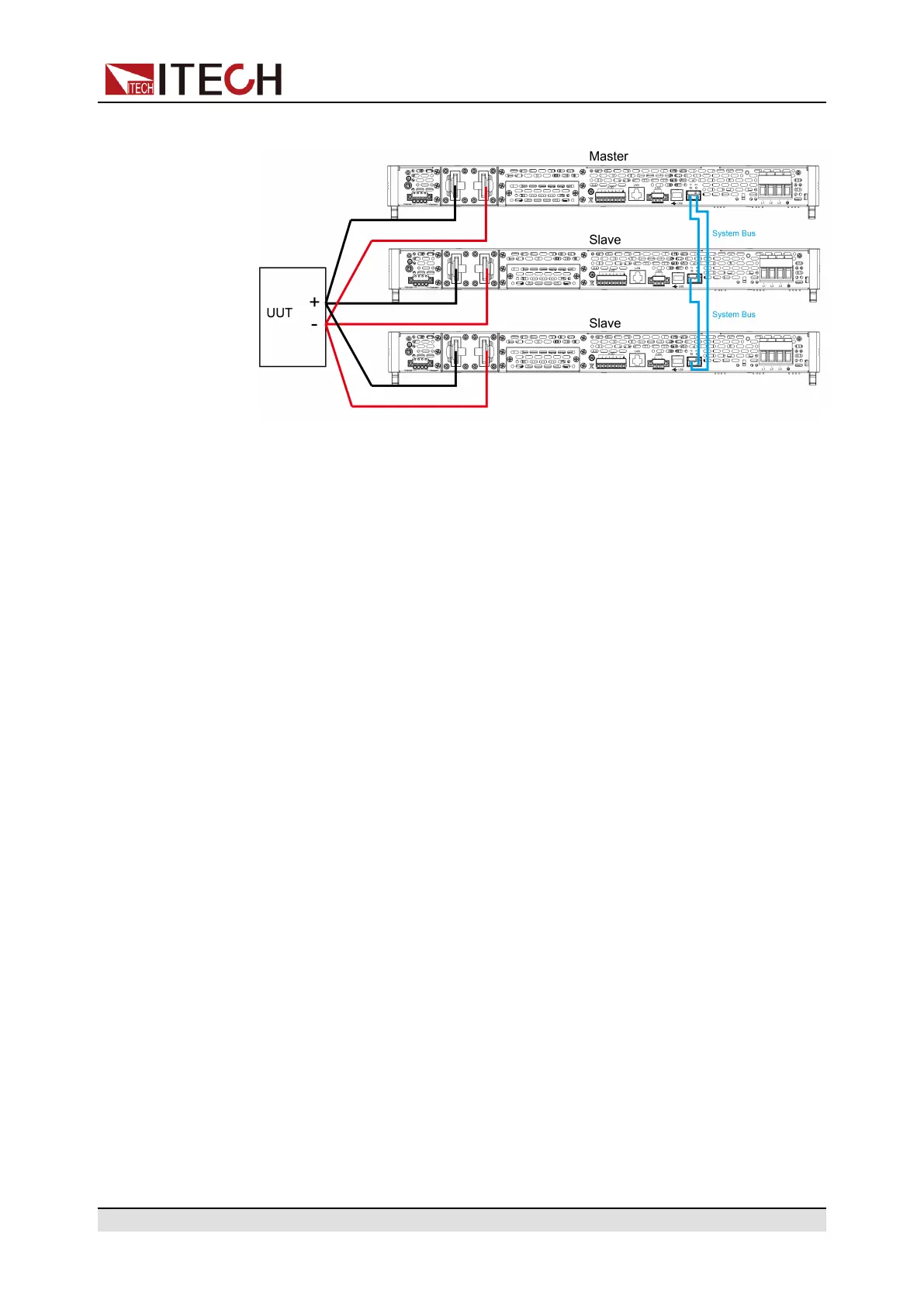
Figure 5–1 Wiring connection diagram
a. Connect the AC input terminals of the three units separately, and connect
them to the AC distribution box.
b. Connect the DC output terminals of the three units in parallel and connect
them to the DUT.
c. Refer to the blue wiring legend in the figure, connect the System Bus (i.
e., the fiber outer ring interfaces TX and RX) for fiber-optic communica-
tion between the master and slaves.
3. Turn on the main switch of the AC distribution box and power on each of the
three units.
4. Set three units in parallel mode with one master and two slaves.
a. Press the composite keys [Shift]+[P-set] (System) on the front panel to
enter the system menu.
b. Set Parallel to Master or Slave and press [Enter].
c. After setting the Master, you need to set Total to 3.
For details, see Configure the Menu Item.
5. After the parallel menu of the three units are set, restart the instrument
separately.
After the instrument is restarted, the VFD shows that the instrument is work-
ing in parallel mode.
Revert to Single Mode
1. Set each of the three instruments to single mode.
a. Press the composite keys [Shift]+[P-set] (System) on the front panel to
enter the system menu.
b. Set the Parallel to Single.
For details, see Configure the Menu Item.
2. Power off the three instruments and turn off the main switch of the AC distri-
bution box.
3. Remove the cables connection of the System Bus and DC output terminals
between three units.
Copyright © Itech Electronic Co., Ltd.
139

 Loading...


