Inspection and Installation
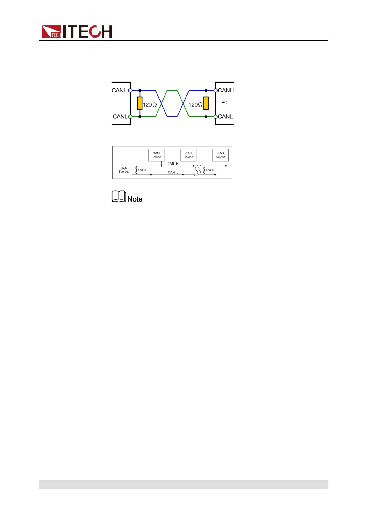
• If the communication signal is poor or unstable, it is recommended to con-
nect a 120 Ω terminating resistance.
– The connection diagram of a single device is as below.
– The connection diagram of multiple devices is as below.
When multiple devices are connected, it is recommended to connect
the pin 8 (GND) of the P-IO terminal on the rear panel of these devi-
ces in parallel, and the communication quality will be improved in the
entire CAN network.
2.5.4 GPIB Interface (Optional)
The GPIB (IEEE-488) interface is assembled in the IT-E176 communication
board. Use a GPIB cable to connect GPIB interfaces of the instrument and PC.
Please ensure that the screws have been screwed down in order to have a full
connection.
GPIB Configuration
Each device on the GPIB (IEEE-488) interface must have a unique whole num-
ber address between 1 and 30. Your computer’s GPIB interface card address
must not conflict with any instrument on the interface bus. This setting is nonvo-
latile; it will not be changed by *RST.
When you purchase the interface accessory and successfully insert it into the
corresponding position on the rear panel of the instrument, the menu item for
changing the GPIB address appears in the System menu. The specific steps
are as follows:
1. Ensure that the instrument's power switch is off, that is, the instrument is in
Power Off state.
2. Insert the separately purchased GPIB interface card into the card slot on the
rear panel of the instrument.
Copyright © Itech Electronic Co., Ltd.
38

 Loading...


