Basic Operation
Level rise slope 10us
Level fall slope 2us
Minimum time width
for low level keep
30us
The bi-direction I/O functions are introduced as below:
• Press [On/Off] on the instrument’s front panel, the instrument’s output is
changed from Off to On. At this point, the pulse signal output from pin 6 can
be detected.
• When the instrument’s [On/Off] is in On state, input pulse signal to pin 6,
and it will not impact the [On/Off] state.
• When the instrument’s [On/Off] is in Off state, when pulse signal is input to
pin 6, the [On/Off] will be changed from Off to ON.
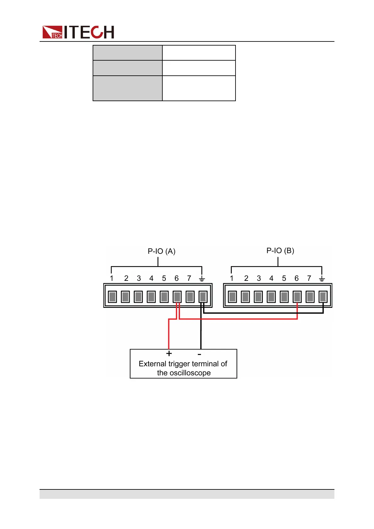
Taking two instruments as an example, the operation is as below:
1. Referring to the figure below, connect pin 6 of two instruments to the exter-
nal oscilloscope.
2. Set pin 6’s function of two instruments to Not-Invert and Sync-On.
3. Confirm that the [On/Off] of both instruments is in Off state.
4. Set the voltage to 10V on the front panel of instrument A, and turn on
[On/Off].
At this time, check the oscilloscope. The instrument A’s pin 6 outputs pulse
signal and the instrument B’s output function is synchronously turned on.
Copyright © Itech Electronic Co., Ltd.
94
 Loading...


