Inspection and Installation
Operation procedures:
• For 1U/2U model, see the steps below to connect the power cable.
1. Confirm that the switch of the AC power distribution box is off.
2. Confirm that the power switch is in the OFF position and verify that there
is no dangerous voltage on the connection terminals.
3. Remove the protective cover outside the AC input terminal on the rear
panel.
4. Connect one end of the power cable’s round terminal to the AC power in-
put terminal on the instrument’s rear panel.
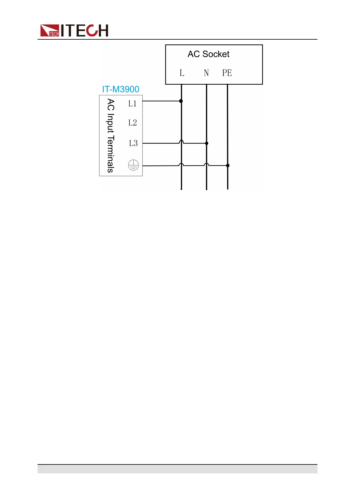
a. You only need to connect the red/green/yellow (or brown/black/gray)
live wires to the terminals on the rear panel, which are not required to
correspond to L1, L2 and L3 terminals one by one.
b. The yellow-green wire is grounding wire, which is connected to the
protective grounding terminal (PE).
5. Mount the protective cover back to its original position.
6. Refer to the suggestion connection diagram, connect the other end of the
power cable to the required AC distribution box.
2.4 Connecting the Device Under Test (DUT)
This section describes how to connect the test cables between the instrument
and DUT.
Copyright © Itech Electronic Co., Ltd.
23
 Loading...


