Service menu
AirModule –6 720 813 268(2014/10)
41
12 Service menu
The user interface menu is automatically adjusted to the system. Some
items are only displayed if they correspond with the system construction
and the user interface is correctly set. Items are only displayed in
systems where corresponding units are installed, e.g. a solar heating
system. You will find corresponding menu posts and settings in the
associated instructions.
For information on how to use the service menu, see Chapter 10 starting
on page 35.
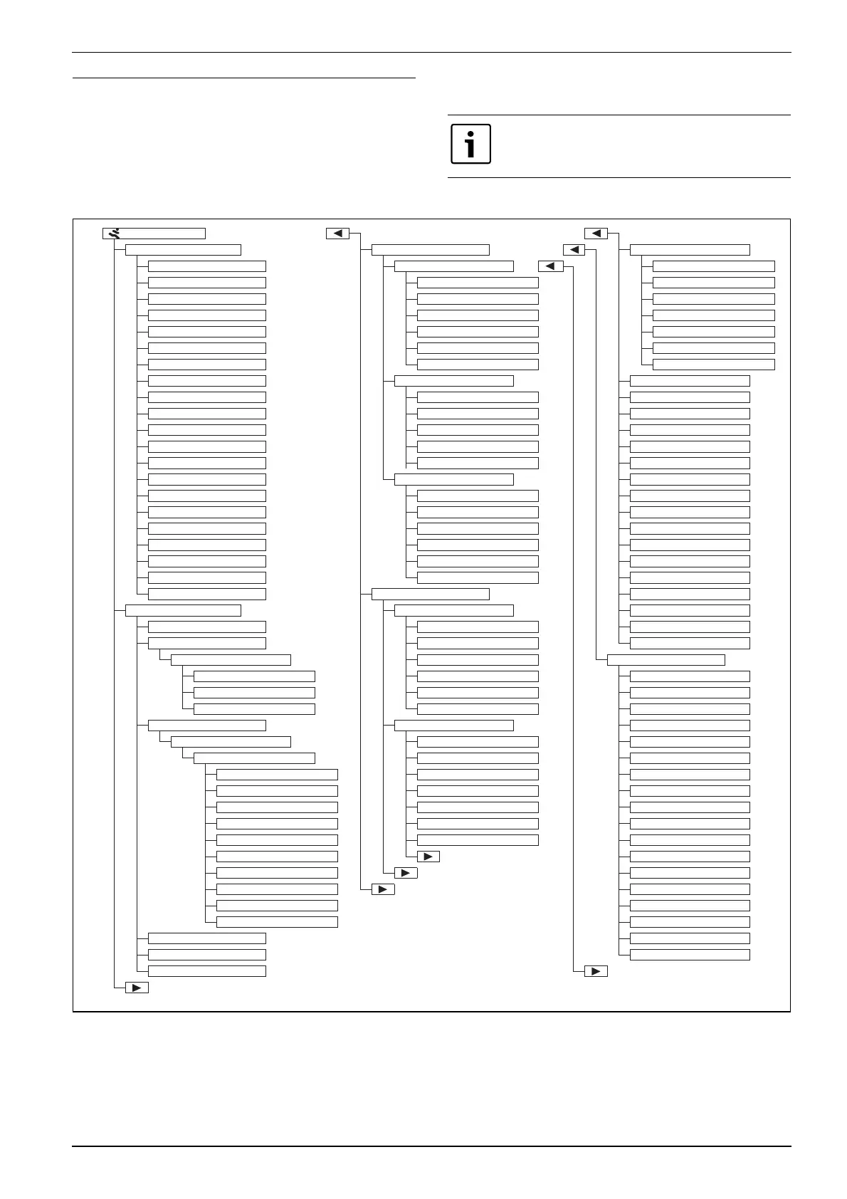
Fig. 36 Service menu overview 1/2
Standard settings are marked in bold in the column
Setting range ( Chapter 12.1 to 12.9).
Service menu
Commissioning Set booster heater Set heating curve
Country information Gen. additional heater settings Design temperature
Storage cylinder Select an external heat source End point
Start configuration wizard Booster heater delay on Base point
Select an external heat source Operating mode according to tariff Max. flow temperature
Immersion heater operating Booster heater only Solar influence
Heating circuit 1 installed (.. 4 ..) Turn off the booster heater Room influence
Config. VK1 on the heat source Max. additional heater temp. Room temperature offset
Mixer heating circuit 1 ... 4 Additional electric heater Heat constantly below
Mixer runtime heat circ. 1 ... 4 Immersion heater operating mode Frost protection
Heating system heat circ. 1 ... 4 Limit comp. output Frost prot. limit temp.
Ctrl type h. circ. 1 ... 4 Limit booster heater heating Heating/Cooling
Prog. unit Heat. circ. 1 ... 4 Limit eff. DHW operation mode Heating mode off
DHW system Outdoor temp. limit Cooling mode off
DHW heat pump 1 Additional heater with mixer Heating direct start limit
DHW circulation pump Mixing valve delay Cooling start delay
Solar thermal sys installed Mixing valve runtime Cooling start delay
Constant temperature Alarm input logic Heating start delay
Pool 3-way valve Outs. temp par. mode Heating start delay
Electr. anode in cylinder Outside temp. exchange operating Room temp. switch diff.
Fuse size Booster heater water heater Dew point temp. diff.
Confirm configuration Set heating/cooling Min. set flow value
Heat pump System data Mixer
Stand-alone mode Storage cylinder Mixing valve runtime
Pumps Config. VK1 on the heat source Shown in standard display
Heat pump 1...2 Internal heating pump Screed drying
Prim. heating pump mode Min. outdoor temperature Activated
Temp.diff. TC3/TC0 heating Damping Dwell time before start
Temp.diff. TC3/TC0 cooling Type of building Start phase duration
External connections Circuit 1 ... 4 Start phase temperature
Heat pump 1...2 Heating circuit installed Heat-up phase step width
External connection 1...3 Prog. unit heat. circ. 1 Heat-up phase temp. diff
Logic ext. connection 1...3 ext. room temp. sensor Holding phase duration
Block compr. operation Heating system heat circ. 1 Holding phase temp.
Block DHW mode Circuit function Cool-dn phase step wdth
Block heating mode Ctrl type h. circ. 1 Cool-down phase t.diff
Block cooling mode Max. flow temperature Endphase duration
Overheating protection VK1 End phase temperature
Energy supply company block 1 Max. interruption time
Energy supply company block 2 Screed dry. system
EVU blocking time3 on Screed dry. H. circ. 1 ... 4
Booster heater block Start
Max. compressor output Cancel
Fuse size Continue
Manual defrosting
6 720 811 136-103.1O
 Loading...