Installation
6 720 643 409 (2010/03)
28
9 Installation
9.1 Collector system
Installation and filling
Installation and filling of the collector system should
comply with applicable laws and regulations. Soil used
for refilling around the collector hose may not contain
stones or other sharp objects. Pressure test the
collector system before refilling to ensure that the
system is airtight.
When cutting the collector, it is important that no dirt or
gravel enters the system. This can cause stoppages in
the heat pump and damage components.
Filling unit
A filling unit is included in the delivery and should be
installed close to the collector circuit inlet.
Expansion vessel, safety valve, pressure gauge
The expansion vessel, safety valve and pressure gauge
are to be provided by the dealer.
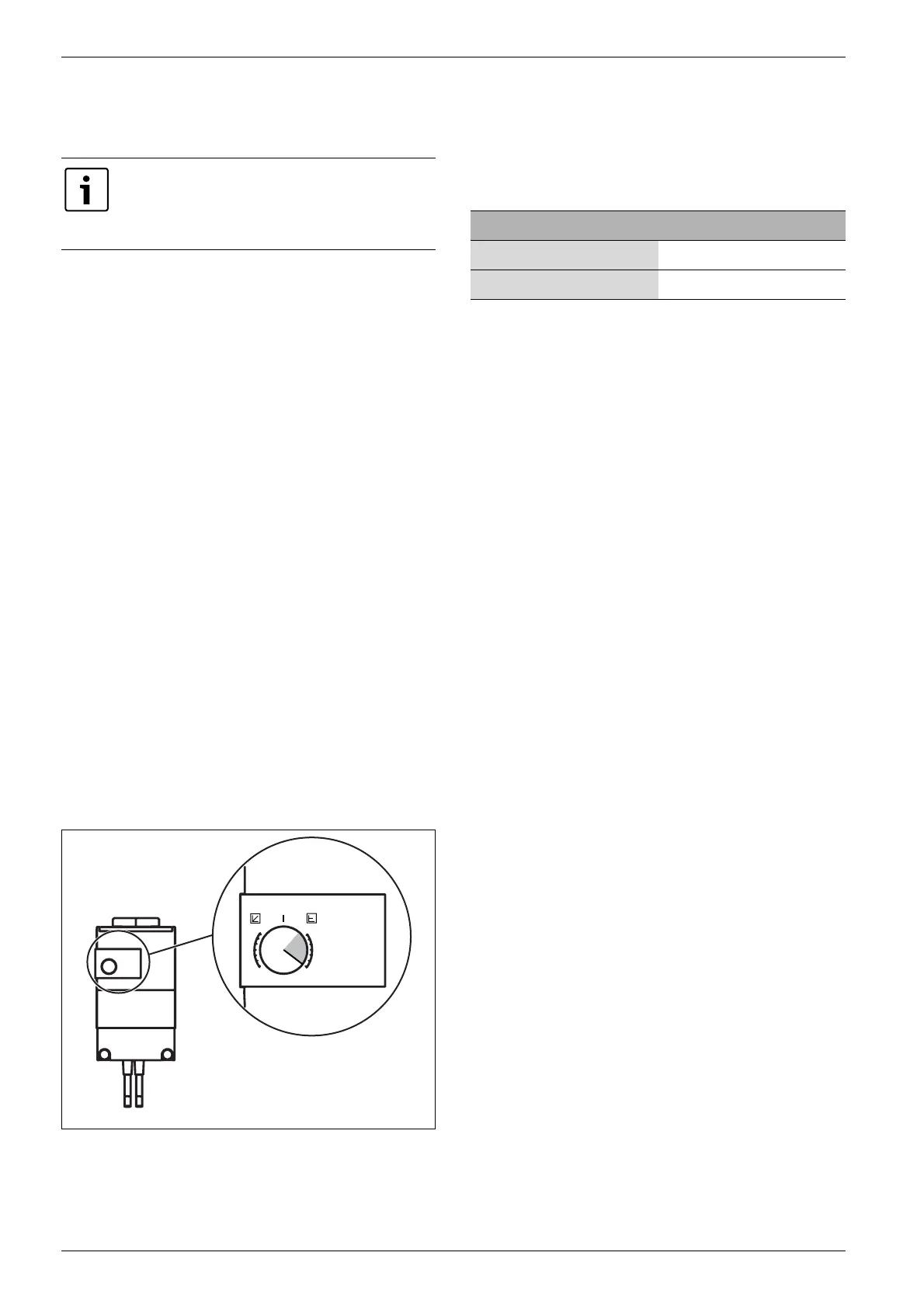
Heat transfer fluid pump
Factory setting for the collector circuit pump is max (Æ
Image 19). The setting may need to be adjusted to
achieve the correct delta value (Æ Chapter 18.4). The
value must lie within the grey area. To adjust the value,
turn the dial.
Fig. 19
Membrane expansion vessel in the collector circuit
Select membrane expansion vessel according to:
Antifreeze/Corrosion preventative
Freeze protection to -15 °C should be ensured. We
recommend the primary use of bio-ethanol, otherwise
propylene glycol.
Only qualified installers may carry out the
installation. The installer must follow
applicable rules and regulations and
recommendations from the supplier.
min
max
min
max
6 720 641 855-34. 1I
ext. in
Model Volume
E6-E11, C6-C11 12 litres
E14 - E17 18 litres
Tab. 18
 Loading...