Electrical connections
6 720 643 409 (2010/03)
44
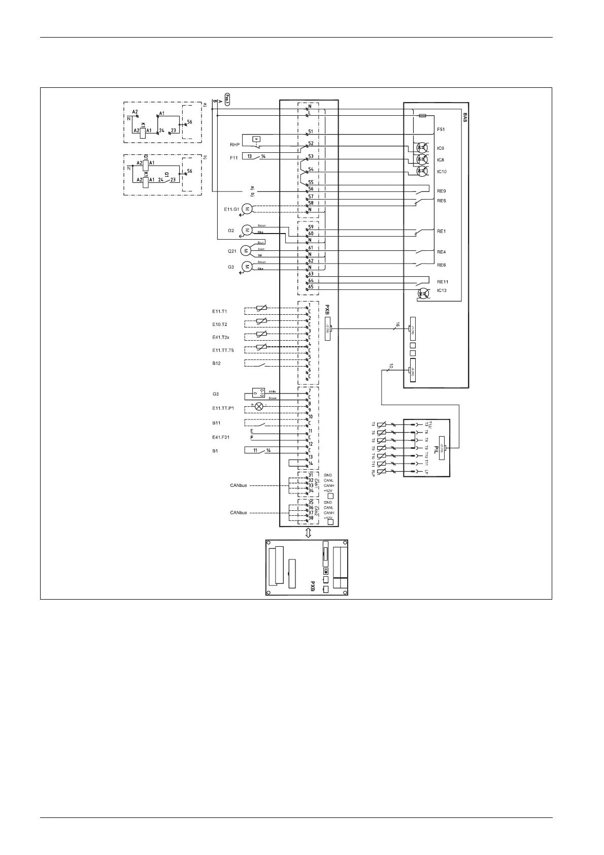
10.4.7 Complete wiring diagram connections E14-E17
Fig. 47 Complete wiring diagram connections
Solid line = factory connected
Dotted line = connect during installation:
RHP High pressure switch
F11 Motor cut-out compressor
Q1 Soft starter (accessory)
K1 Contactor compressor
E11.G1 Circulation pump circuit 1
G2 Heat carrier pump
G3 Heat transfer fluid pump
Q21 3-way valve
F51 Glass fuse 6.3A
E11.T1 Flow
E10.T2 Out
E41.T3x Hot water E model
E11.TT.T5 Room sensor, circuit 1
B12 External input 2
E11.TT.P1 LED room sensor
B11 External input 1
E41.F31 Alarm protective anode
B1 Alarm phase meter
E41.T3 Hot water C-model
T6 Hot gas
T8 Heat transfer fluid out
T9 Heat transfer fluid in
T10 HTF (coll) in
T11 HTF (coll) out
RLP Low pressure switch
a) Delivery version
b) 14-17kW Soft starter
6 720 641 855-30.1I
 Loading...