8/18
IDENTIFICATION
(Part no. - Description)
FILTER (Mesh)
NOZZLE
TYPE
(1197536) JEF 11002
YELLOW
(1197476) JSF 11002
YELLOW
(1197535) JEF 110015
GREEN
80 (Zinc yellow)
50(Gentian blue)
50(Gentian blue)
80 (Zinc yellow)
50(Gentian blue)
50(Gentian blue)
50(Gentian blue)
50(Gentian blue)
50(Gentian blue)
50(Gentian blue)
50(Gentian blue)
50(Gentian blue)
80 (Zinc yellow)
80 (Zinc yellow)
50(Gentian blue)
(1197475) JSF 110015
GREEN
(1197537) JEF11003
BLUE
(1197477) JSF11003
BLUE
Herbicides
30
30
0.13 GPM
(0.49 L/min)
30
30
30
30
APPLICATION
PRESSURE
(psi)
FLOW RATE
gpm (L/min)
(1197565) JHC 8002
YELLOW
45
(1198892) JHC 8004
RED
45
(1198893) JHC 8005
BROWN
45
(1197486) JDF 04
RED
(1197497) JAI 120015
GREEN
(1197488) JDF 06
GREY
(1197501) JAI 12003
BLUE
(1197487) JDF 05
BROWN
(1197499) JAI 12002
YELLOW
15
20
15
20
15
20
Fungicide,
insecticide
and
foliar
fertilizers
Herbicides
and
foliar
fertilizers
Herbicides
Herbicides
*Approximate data based on a spray swath for unique nozzles at
20 inch height of the target.
8. Operating Instructions
The following steps describe how to safely use the sprayer.
8.1. Select the correct nozzle
8.2. Calibration of battery powered back-
pack sprayer
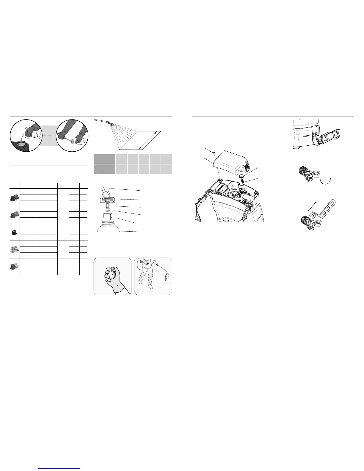
PROCEDURE
1. USING CALIBRATOR BOTTLE (OPTIONAL)
2. Hold the lance at the working height and spray to mea-
sure the application band width.
3. Based on the band width, calculate the total walking dis-
tance required to spray the desired area. Use the chart as
shown next.
Band
width
Lance
Cover
Filter
Nozzle
Nozzle cap
Calibrator
bottle
• Attach the calibrator bottle to the lance as shown:
• Remove the cap, nozzle and lter.
• Mount the calibrator cover to the lance.
• Reinstall the lter, nozzle and cap.
• Screw the calibrator onto the cover.
Record the time it takes to walk
340 sq/ft (1/128th acre)
Simulate the spraying of 340
sq/ft (1/128th acre)
1. Hold the lance at the normal working height and spray
into the bottle while walking the distance required to
spray an area corresponding to 340 sq/ft (1/128th acre).
2. Place the bottle on a level surface and observe the liquid
level visible through the side of the bottle. The ounces
collected corresponds to gallons per acre. For example if
you collected 10 ounce while spraying 340 sq/ft this equal
10 GPA.
3. Empty the bottle and repeat this operation to determine
the average of two or more readings.
Band width
ft (m)
1.6
(0.5)
2.2
(0.7)
3.2
(1.0)
3.9
(1.2)
4.9
(1.5)
Distance to
walk ft (m)
164
(50.5)
117.1
(35.7)
82.0
(25.0)
68.2
(20.8)
54.7
(16.7)
NOTE: This sprayer is packaged with the JD-12P nozzle installed
on the lance. Other nozzles mentioned in this manual are optio-
nal, and do not accompany this sprayer.
0.17 GPM
(0.65 L/min)
0.26 GPM
(0.98 L/min)
0.13 GPM
(0.49 L/min)
0.17 GPM
(0.65 L/min)
0.21 GPM
(0.80 L/min)
0.22 GPM
(0.85 L/min)
0.15 GPM
(0.57 L/min)
0.11 GPM
(0.42 L/min)
0.37 GPM
(1.39 L/min)
0.30 GPM
(1.15 L/min)
0.24 GPM
(0.92 L/min)
0.53 GPM
(2.00 L/min)
0.42 GPM
(1.60 L/min)
0.26 GPM
(0.98 L/min)
13/18
2. Remove screw A;
3. Remove base cover B;
4. Unscrew lter cover C;
5. Clean or replace ltering element D.
A
B
C
D
• Only ll the tank with a water soluble agrochemical or an al-
ready mixed powder liquid form through the lling lter. Do
not prepare mixtures directly in the sprayer tank;
• This sprayer is an electronic tool and must be protected from
severe environmental conditions. When not using, do not
leave the sprayer in sun, rain or frost;
• Do not submerge the sprayer completely or partially;
• After nishing the application, clean and wash all equipment
in an approved decontamination area;
• Clean the sprayer before storage. Circulate fresh water
through the tank, pump and hoses after each use. This will
help remove chemical residues and extend life of sprayer
parts;
• The spray lance can be conveniently stored on the clips on
the side of the tank;
• Ensure that there is no liquid waste in the sprayer, especially
in harsh winter locations;
• Nozzles and lters must be periodically cleaned or replaced.
Do not clean nozzles or lters with sharp hard objects, nor
blow through them using the mouth.
• Turn it 180° as shown in B;
• Insert the maintenance key according to the illustration C;
• Next, unscrew the agitator counterclockwise until the lever
is removed;
• Put 1.3 gallons (5 L) of water in the tank and turn on the sys-
tem to clean the system;
NOTE: Discard the water used to clean the system in an appro-
priate location.
• Inspect the agitator needle and replace lever assembly if ne-
cessary. (refer to illustrated parts list);
• After cleaning the system, reinstall the agitator lever and nee-
dle by reversing the steps. Check for any leaks before starting
to spray.
A)
B)
C)
9.1. Maintenance of the agitation system
• Turn o the sprayer, then move the agitation lever to the ho-
rizontal position as shown in A;
 Loading...