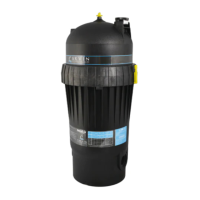
SERIES LASER FILTERS FOR IN-GROUND
AND ABOVE-GROUND SWIMMING POOLS
Operation/installation instruction
Before installation be sure toread allinstructions andwarnings carefully. Refer to product
label(s) for additional operation instruction and specifications.
IMPORTANT: This product has been carefully inspected and packed at our factory.
As the carrier has assumed full responsibility for its safe arrival, any claim for damage to
the shipment, either visible or concealed, must be made on the carrier. Check that the
equipment is correct for the particular installation.
Your filter is a pressure vessel and should never be serviced
while under pressure. Always shut off pump to relieve the
pressure in the filter prior to servicing the unit.
To reduce risk of injury, do notpermit children to use this
product unless they are closely supervised at all times.
Locate the system at least five feet (1.5 m) from the pool
to prevent it being used as a means of access to the pool
by young children. (See ANSI/NSPI-8 1996 “Model Bar-
rier Code For Residential Swimming Pools, Spas and Hot
Tubs”).
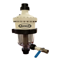
PUMP SELECTION
A full line of pool pumps are available for installation with these filters. For those
installations where the equipment will be placed above the water level, a self-priming
pump should be selected. Ask your dealer to determine the proper size and distance from
pool or spa and friction losses (restrictions) of associated equipment. The filter system
is assembled at the site from a filter module and a pump module. This arrangement
permits a choice of pump to suit a FLOW RATE of 20 US gallons per minute per square foot
of filter area (equal to a WATER VELOCITY OF 0.0133 m/s).
When using a pump with a line cord:
Risk of electric shock! Connect plug only into a receptacle
protected by a ground fault circuit interrupter (GFCI).
Do not use an extension cord! Protect the cord from
abuse but do not bury it.
If the pump cord is damaged or appears to be
damaged, replace it immediately with the same typeof
cord which is available from your local dealer. The new
cord must be installed by a qualified electrician. Inspect the cord annually.
To reduce the risk of electric shock, do not use an ex-
tension cord to connect unit to receptacle.
Do not bury cord. Locate cord to minimize abuse from
lawn mowers, hedge trimmers and other lawn equipment.
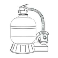
The filter module is equipped with a dial valve which works as follows:
1. FILTER gives a downward flow through the filter bed. Dirt accumulates in the sand as fil-
tering proceeds, and gradually restricts the flow of water until backwashing is necessary.
This position can also be used for vacuuming.
2. BACKWASH gives an upward flow through the filter bed that removes the dirt from the
sand and carries it to the waste.
3. DRAIN is for pumping water from the pool. It allows the flow from the pump to bypass
the filter and go directly to the waste. You can also use this position to vacuum heavy con-
centrations of debris.
4. WHIRLPOOL bypasses the filter to obtain the optimum performance from a
hydro-air fitting fed by the filter pump. (No filtration occurs in this position).
5. WINTERIZE allows air to leave or enter the tank to help priming and draining.
Only to be used when pump is off.
6. RINSE gives a downward flow that settles the filter bed after backwashing and
carries any remaining loose dirt to the waste.
7. TEST prevents only backflow of water from pool during pump maintenance if filter
is below water level.
FILTER SAND
The outstanding filtration and superior dirt-holding capacity of this filter depends on the
use of the proper grade of filter sand. It should meet the following specifications: The
filter sand must be free of clay, loam, dirt and organic matter, and must consist of hard,
durable, rounded or sub-angular grains of silica sand with no more than 1% of flat or mi-
caceous particles.
The grains should have an effective size of 0.44mm with a uniformity
coef-
ficient of 1.35. DO NOT USE "SANDBOX" SAND. The filter sand is NOT included in the filter
module and must be purchased separately. Refer to table 1for the quantity required. Do not
fill the tank with sand before the filter is in its final position. Keep the sand dry for easy in-
stallation. Use only the approved filter sand, otherwise the system may not work satisfac-
torily.
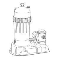
INSTALLATION LOCATION
Locate the system as close to the pool as possible, but keep at a distance of at least five
feet (1.5 m). (See previous warning). Locate the system on a hard, level surface,
preferably in a dry, shaded, and well-ventilated area. Give consideration to the following:
Position of suction, return, and waste connections; Access for backwashing and servicing;
Protection from the sun, rain, splashing, etc; Drainage of filter room or pit; Ventilation and
protection of the motor.
ASSEMBLY OF SYSTEM
1. Place
the empty tank in position on the base. Press the tank down until it engages the base.
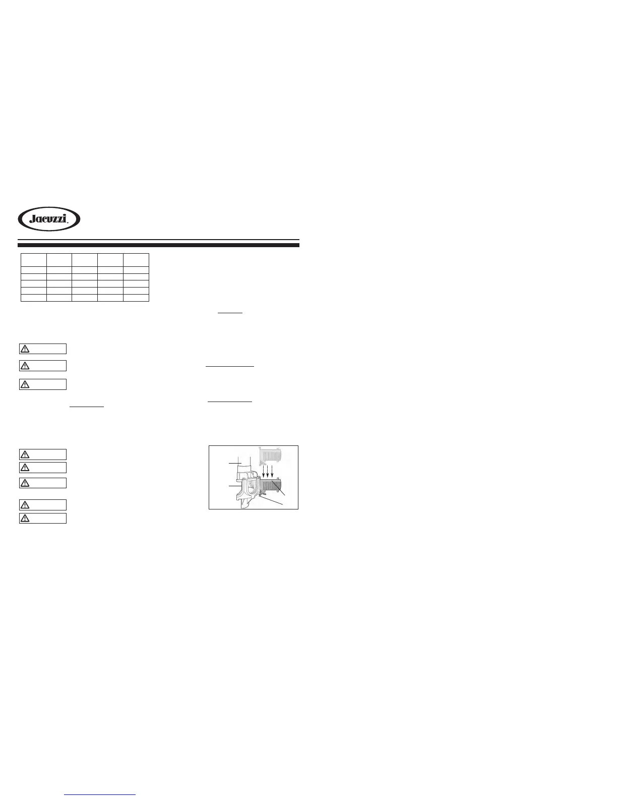
2. If the laterals are not installed, hold the standpipe/manifold assembly so that the
manifold is located in the middle of the tank. Take one of the lateral flow tubes in your other
hand and lower it into the tank, sliding it down the tube and into one of the grooves in the
manifold until a snap-fit is obtained. Repeat this action until all eight lateral flow tubes are
installed, then lower the complete assembly down to the bottom of the tank. Press it down
to ensure that the central tube is seated in the depression in the base of the tank. See fig-
ure 1.
3. Place the sand fill cover
over the tank opening to
prevent the sand from
getting into the standpipe.
See figure 2.
4.
Fill the tank approximately
1/2 full of water.
5. Pour the recommended
amount of sand into the
tank, making sure that
the standpipe remains
centered and vertical.
Level the surface upon
completion.
6. Remove the sand-fill cover.
7. Preassemble the clamps with one screw and one nut, turning the screw 3-4 turns only.
See Figure 3.
8. Carefully remove all sand particles from the valve mounting surfaces.
9. Place the O-Ring onto the bottom of the valve body.
10.
Lower the dial valve carefully into position so that its underside engages with
the standpipe. Rotate the valve until the inlet is approximately in line with the pump.
11.
Place clamps around tank and valve neck and assemble second screw and nut.
12. Firmly tap with a rubber mallet outside of the clamps as you tighten both screws
alternately and evenly.
13.
Make sure screws are tightened until clamps are completely closed. See figure 4.
14.
Install the pressure gauge into the threaded opening in the dial valve.
15.
Install the backwash adapter, if necessary, to reduce backwash flow.
 Loading...