Attention
Emergency stop
input circuit to
Motor driver
power circuit
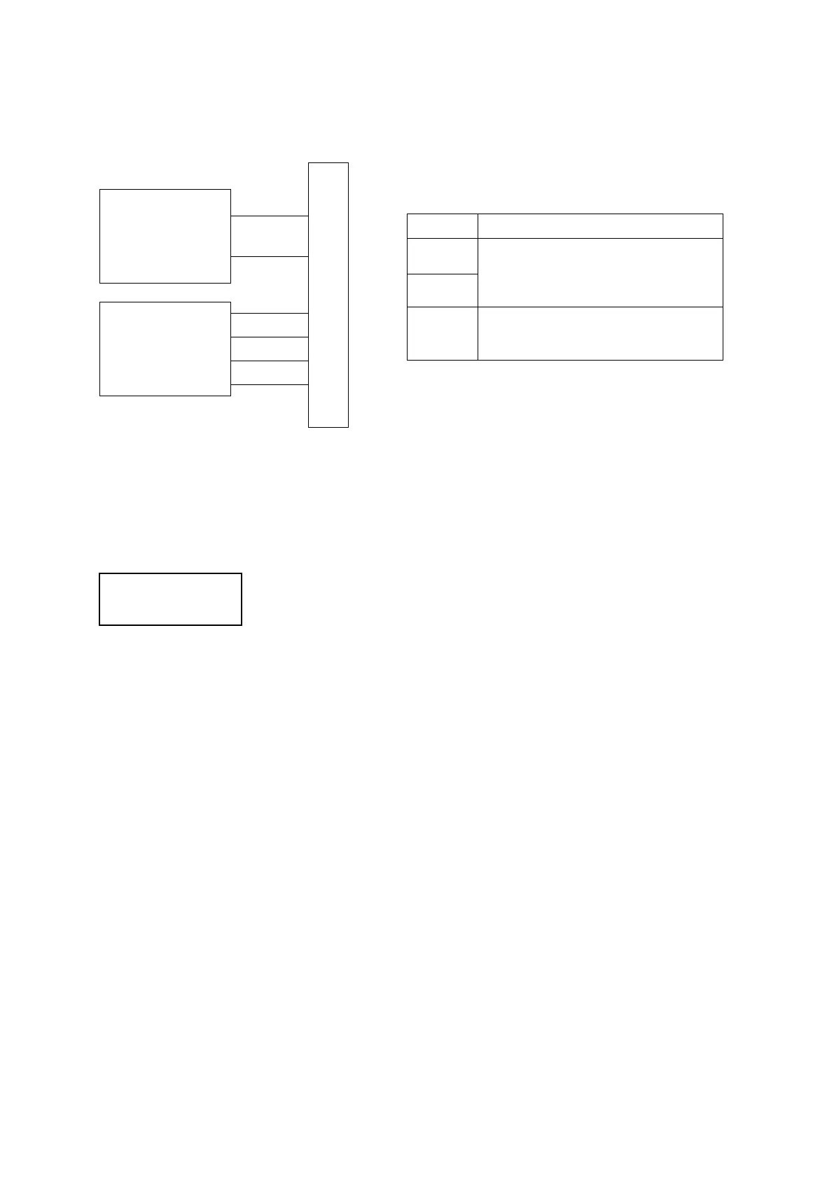
18.3 Circuit Diagram
To connect the emergency stop switch, connect it between pins 15 – 16 and 11 – 12. Use a normal
close switch as the connection point.
If connecting the emergency stop switch between pins 11 – 12, please short pins 13 – 14.
Please be careful as making connections under any conditions, other than
those above will damage the emergency stop circuit.
The output current of the photocoupler is no more than 100mA.
Please do not use any pins other than the ones above.
Pin No. Function
15
Emergency stop input to CPU (a
signal so the robot can recognize
whether or not the emergency stop
16
11 – 14 Motor driver power supply relay input
105
 Loading...