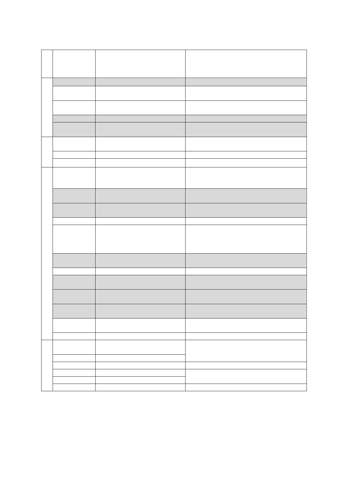
EasyManua.ls Logo

Janome JR3303N-AJ User Manual

Janome JR3303N-AJ
134 pages
To Next Page IconTo Next Page
To Previous Page IconTo Previous Page
Page #108 background imageLoading...
Page #108 background image
Specifications
Desktop Robot JR3000
Category
Command Necessary Parameter Description
Delay
delay
Delay Time
Stop for the exact specified time.
dataIn
Numeric Variable Name, Input
Bit Number, Input Source
Read numeric data from the I/O.
dataInBCD
Numeric Variable Name, Input
Bit Number, Input Source
Read numeric data in BCD from the I/O.
waitStart
Wait for a start instruction.
waitStartBZ
Wait for a start instruction while sounding
the buzzer.
Pallet
loopPallet
Pallet Routine Number, go Point
Number
Pallet loop
resPallet
Pallet Routine Number
Reset the pallet counter.
incPallet
Pallet Routine Number
Increase the pallet counter number. (+1)
Execute Flow Control
callBase
At a user-defined point with a point job
number set to it, call the point job defined by
that point type.
callJob
Point Job Number
Subroutine call point job data specified by
number.
callPoints
Variable Name (Identifier)
Perform a specified point string (defined in
Customizing Mode).
returnJob
End of point job
returnFunc
Return Value (Expression)
Terminate the function by assigning the
value of the specified expression as a return
value. (This command is valid with functions
only.)
callProg
Program Number
Subroutine call a program specified by
number.
endProg
End of program
goPoint
Condition Number, go Point
Number
Jump to a specified point.
goRPoint
Condition Number, Relative go
Point Number
Jump to a relatively-specified point.
goCRPoint
Condition Number, Relative go
Point Number
Jump to a selected destination during a CP
movement.
jump
Jump destination, Label
Number
Jump to a specified label.
Label
Label Number
Label
For, do-loop
for
Variable Name, Initial Value,
End Value, Step Value
Repeat commands between for and next
until the specified variable changes from the
initial value to the end value.
next
exitFor
Break from the for loop.
do
Repeat commands between do and loop.
loop
exitDo
Break from the do loop.
107

Table of Contents

Question and Answer IconNeed help?

Do you have a question about the Janome JR3303N-AJ and is the answer not in the manual?

Janome JR3303N-AJ Specifications

General IconGeneral
BrandJanome
ModelJR3303N-AJ
CategorySewing Machine
LanguageEnglish

Summary

PREFACE

FOR YOUR SAFETY

1. LINEUP

2. IDENTIFICATION PLATE

2.1 Reading the Identification Plate (Sample)

Describes how to read the sample identification plate on the robot.

2.2 Identification Plate Locations

Shows the locations of the identification plates on different robot series.

3. I/O Polarity

3.1 I/O Polarity

Explains the two types of I/O polarity (NPN and PNP) and power supply indications.

4. EXTERNAL DIMENSIONS

4.1 Unit External Dimensions

Provides detailed external dimension diagrams for various robot models.

4.2 Unit Fixtures (4 locations)

Details the mounting points and fixture locations on the robot base.

4.3 Teaching Pendant (Optional)

Specifies installation height recommendations for the teaching pendant.

4.4 Switchbox

Shows installation height recommendations and dimensions for the switchbox.

5. RANGE OF MOVEMENT

6. ATTACHING EQUIPMENT

7. I/O-SYS

7.1 Connectors

Explains I/O polarity and power supply indications for the I/O-SYS.

7.2 Pin Nos. (Robot Side)

Lists the pin numbers and their corresponding insulator colors for the I/O-SYS.

7.3 Cable Wiring

Provides a table detailing cable wiring with pin numbers and insulator colors.

7.4 Output Capacity

Specifies the output capacity (voltage and amperage) for internal and external power supplies.

7.5 Input Signal (NPN)

Shows circuit diagrams for NPN input signals with external and internal power supplies.

7.6 Output Signal (NPN)

Shows circuit diagrams for NPN output signals with external and internal power supplies.

7.7 Circuit Diagram (NPN)

Detailed circuit diagrams for NPN input and output signals.

7.8 Input Signal (PNP)

Shows circuit diagrams for PNP input signals with external and internal power supplies.

7.9 Output Signal (PNP)

Shows circuit diagrams for PNP output signals with external and internal power supplies.

7.10 Circuit Diagram (PNP)

Detailed circuit diagrams for PNP input and output signals.

8. I/O-SYS FUNCTION ASSIGNMENT

9. FIELDBUS FUNCTION ASSIGNMENT

10. I/O-1 (Optional)

10.1 Connector

Explains I/O polarity and power supply indications for the I/O-1 connector.

10.2 Pin Nos. (Robot Side)

Lists pin numbers and their corresponding names for the I/O-1.

10.3 Function Assignment List

Details function assignments for input, output, and other categories for I/O-1.

10.4 Cable Connection

Provides a table for cable connection details, including pin numbers and colors.

10.5 Power Supply Capacity

Specifies the power supply capacities for I/O-1 output and input pins.

10.6 Input Signal (NPN)

Shows circuit diagrams for NPN input signals with external and internal power supplies for I/O-1.

10.7 Output Signal (NPN)

Shows circuit diagrams for NPN output signals with external and internal power supplies for I/O-1.

10.8 Circuit Diagram (NPN)

Detailed circuit diagrams for NPN input/output signals for I/O-1.

10.9 Input Signal (PNP)

Shows circuit diagrams for PNP input signals with external and internal power supplies for I/O-1.

10.10 Output Signal (PNP)

Shows circuit diagrams for PNP output signals with external and internal power supplies for I/O-1.

10.11 Circuit Diagram (PNP)

Detailed circuit diagrams for PNP input/output signals for I/O-1.

11. I/O-S (Optional)

11.1 Connector

Shows the I/O-S connector locations on different robot series.

11.2 Pin Nos. (Robot Side)

Lists the pin numbers for the I/O-S connector.

11.3 Safety Device

Explains connecting safety devices and short-circuiting the connector when not used.

12. FIELDBUS (OPTIONAL)

12.1 Fieldbus Settings

Describes how to set up Fieldbus module types using the teaching pendant or PC.

12.2 DeviceNet

Details DeviceNet connector diagram, network/module status LEDs, and pin assignments.

12.3 Profibus

Details Profibus connector diagram, operation/status LEDs, pin assignments, and settings.

12.4 CC-Link

Details CC-Link connector diagram, run/error LEDs, pin assignments, and settings.

13. I/O-MT (OPTIONAL)

13.1 Connector

Shows the I/O-MT connector locations on different robot series.

13.2 Pin No. (Robot Side)

Lists pin numbers for the I/O-MT connector.

13.3 Function Assignment

Details function assignments for MT1 and MT2 inputs, outputs, and pulse outputs.

13.4 Cable Wiring

Provides cable wiring details for the I/O-MT connector.

13.5 Output Capacity

Specifies output capacities for I/O-MT pins and input signal requirements.

13.6 Input Signals

Shows circuit diagram for I/O-MT input signals.

13.7 Output Signals

Shows circuit diagram for I/O-MT output signals.

13.8 Circuit Diagram

Detailed circuit diagrams for I/O-MT input and output signals.

14. MEMORY PORT

14.1 Teaching Data Backup

Explains how to record and retrieve teaching data using USB memory.

14.2 System Software and PS Data (Model Setting Data) Updates

Describes how to update system software and PS data via USB memory.

14.3 MEMORY Port Settings (Administration Settings Mode)

Details settings for the memory port and auto-update functions.

15. LAN PORT

15.1 Connector

Describes the standard Ethernet connector and its functions.

15.2 Pin Nos. (Robot Side)

Lists the pin assignments for the LAN port.

16. COM 1 – 3

16.1 Connector

Shows the locations of COM1, COM2, and COM3 connectors on robot series.

16.2 Pin Nos. (Robot Side)

Lists the pin numbers for the COM ports.

16.3 COM Connector Pin Connection

Details pin connection mappings for COM ports to PC (D-Sub 9/25 pin).

17. TPU (TEACHING PENDANT CONNECTOR)

17.1 Connector

Shows the location of the teaching pendant connector on robot series.

17.2 Pin Nos. (Robot Side)

Lists pin numbers for the teaching pendant connector.

17.3 Pin Connections

Details RS422 interface pin connections for the teaching pendant.

17.4 Circuit Diagram

Circuit diagram for the teaching pendant connector, including safety circuit.

18. SWITCHBOX CONNECTOR (SWITCHBOX SPECIFICATIONS)

18.1 Connector

Shows the location of the switchbox connector.

18.2 Pin Nos. (Robot Side)

Lists pin numbers for the switchbox connector.

18.3 Circuit Diagram

Circuit diagram for the switchbox connector, including emergency stop and motor driver inputs.

19. COMMAND LIST

19.1 Point Job Data

Lists commands for ON/OFF Output Control and Condition.

19.2 Execute Conditions

Lists commands related to execute conditions.

19.3 PLC Programs

Lists commands for PLC programs (Contact Point, Coil, Connection, Others).

20. VARIABLE LIST

21. FUNCTION LIST

22. SYSTEM FLAG LIST

23. ERROR MESSAGE LIST

24. SPECIFICATIONS

Related product manuals