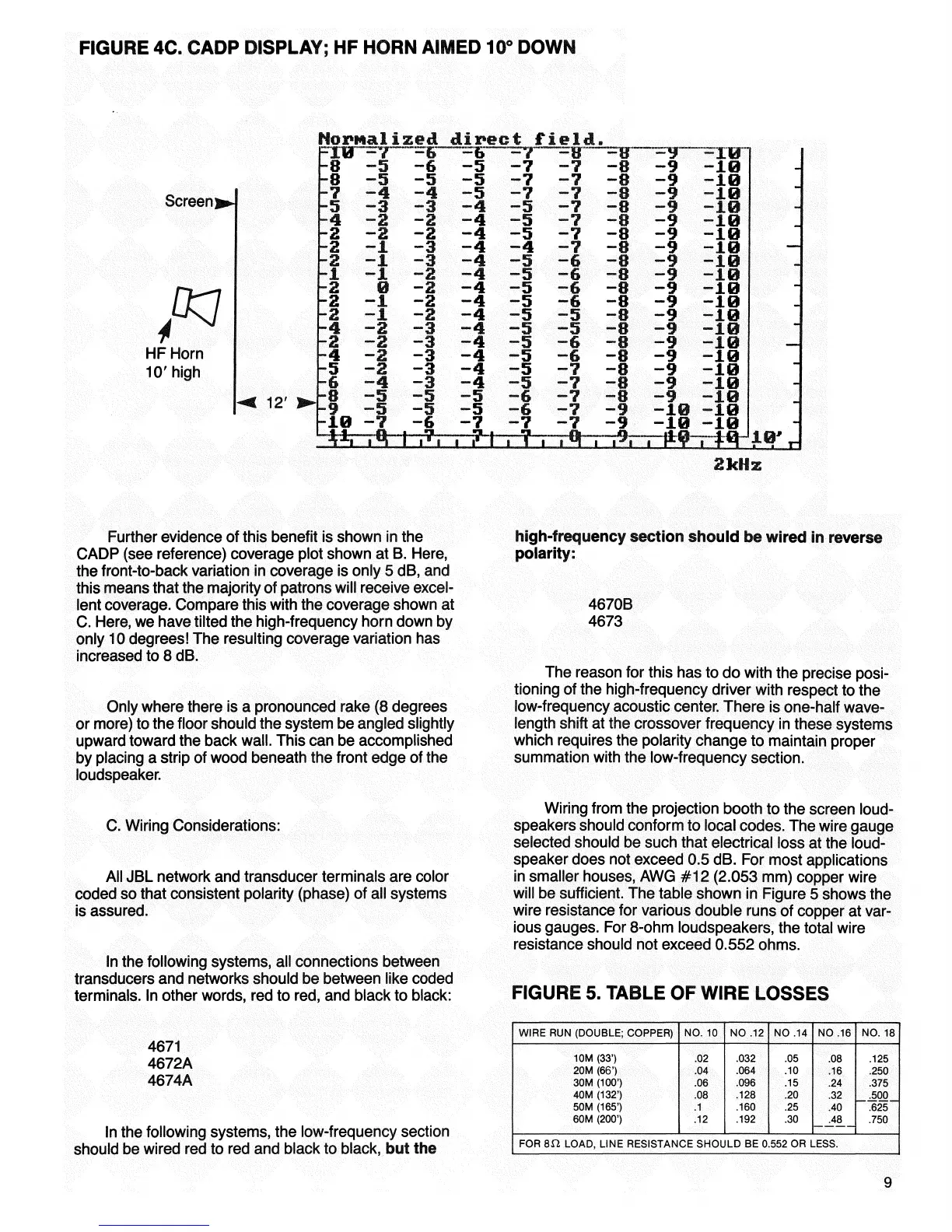
FIGURE 4C. CADP DISPLAY; HF HORN AIMED 10° DOWN
Screen]
HF Horn
10'high
12'
2kHz
Further evidence of this benefit is shown in the
CADP (see reference) coverage plot shown at B. Here,
the front-to-back variation in coverage is only 5 dB, and
this means that the majority of patrons will receive excel-
lent coverage. Compare this with the coverage shown at
C. Here, we have tilted the high-frequency horn down by
only 10 degrees! The resulting coverage variation has
increased to 8 dB.
Only where there is a pronounced rake (8 degrees
or more) to the floor should the system be angled slightly
upward toward the back
wall.
This can be accomplished
by placing a strip of wood beneath the front edge of the
loudspeaker.
C. Wiring Considerations:
All JBL network and transducer terminals are color
coded so that consistent polarity (phase) of all systems
is assured.
In the following systems, all connections between
transducers and networks should be between like coded
terminals. In other words, red to red, and black to black:
high-frequency section should be wired in reverse
polarity:
4670B
4673
The reason for this has to do with the precise
posi-
tioning of the high-frequency driver with respect to the
low-frequency acoustic center. There is one-half wave-
length shift at the crossover frequency in these systems
which requires the polarity change to maintain proper
summation with the low-frequency section.
Wiring from the projection booth to the screen
loud-
speakers should conform to local codes. The wire gauge
selected should be such that electrical loss at the
loud-
speaker does not exceed 0.5 dB. For most applications
in smaller houses, AWG #12 (2.053 mm) copper wire
will be sufficient. The table shown in Figure 5 shows the
wire resistance for various double runs of copper at var-
ious gauges. For 8-ohm loudspeakers, the total wire
resistance should not exceed 0.552 ohms.
FIGURE 5. TABLE OF WIRE LOSSES
4671
4672A
4674A
In the following systems, the low-frequency section
should be wired red to red and black to black, but the
WIRE RUN (DOUBLE; COPPER)
NO.
10
NO
.12
NO
.14
NO
.16
NO.
18
10M
(33')
.02
.032
.05
.08
.125
20M
(66')
.04
.064
.10
.16
.250
30M
(100')
.06
.096
.15
.24
.375
40M
(132')
.08
.128
.20
.32
.500
50M
(165') .1
.160
.25
.40
.625
60M
(200')
.12
.192
.30
.48
.750
FOR
8H LOAD,
LINE
RESISTANCE SHOULD BE 0.552 OR LESS.
9
Nornalized direct field.
 Loading...