Installing the Encoder
1) Install the encoder mount.
2) Install the encoder onto the encoder bracket
and tighten. Do not place it into the machine.
3) Slide the encoder into the coupling
approximately .225” and tighten. Be careful not
to strip the small bolt.
NOTE: The shaft must not protrude into the
slotted section of the coupler or it will not be
able to ex properly.
4) Position this assembly into the bender as
shown. Do not tighten the 1/4” bolts. Adjust the
encoder threaded rod up or down so that when
tighten, the encoder’s shaft only extends into it
approximately .225” also.
5) Securely tighten the encoder stud’s 3/4” nut.
6) Tighten the 1/4” bracket bolts being careful not
to force the coupler out of alignment.
7) Tighten the coupler’s upper socket head bolt.
8) Rotate the spindle by hand and verify coupler
does not show signs of excessive misalignment.
Max run out is .020” total over 360
o
.
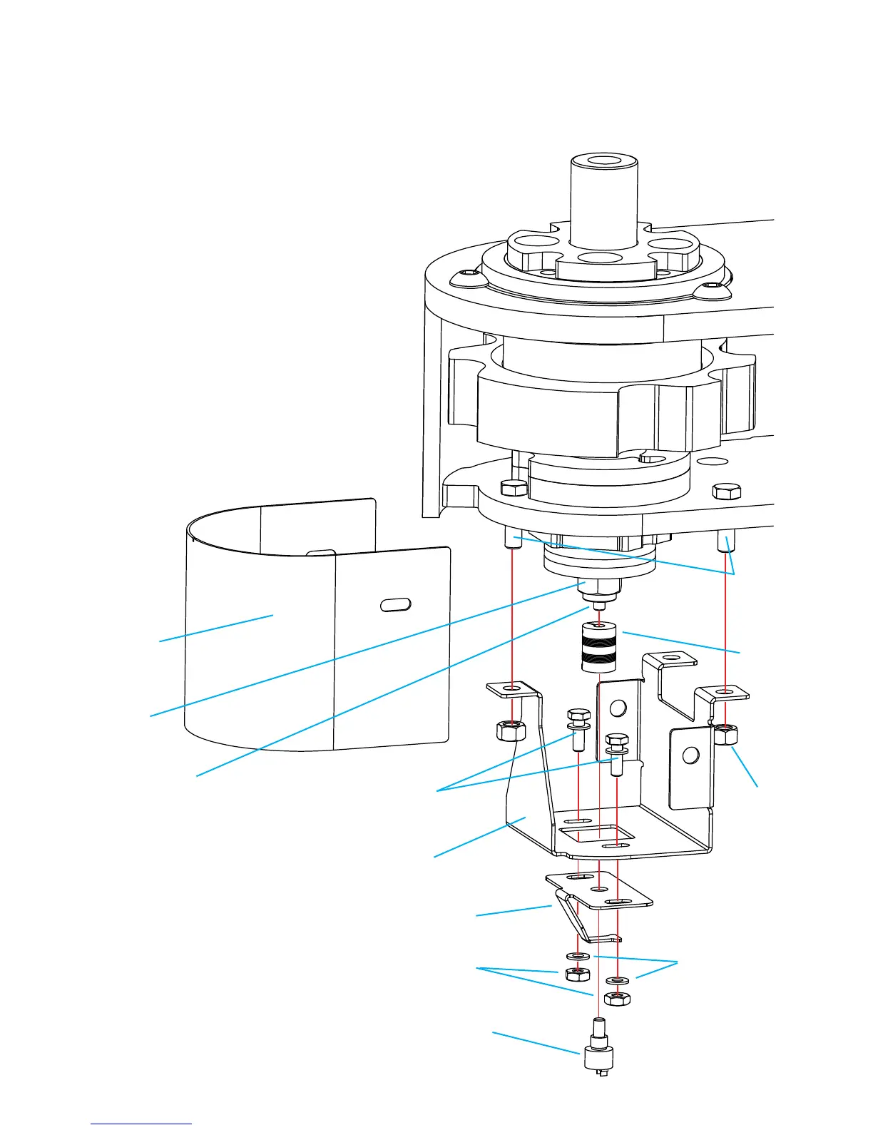
1/4” hex nuts
1/4” washers
1/4”-20 x 3/4” bolt
& 1/4” washers
Absolute position encoder
(Installed with a thin nut that is
not shown)
Encoder
coupling
Encoder bracket
3/8” x 1”
bolts (3x)
3/8” hex nuts
(3x)
Encoder guard
Encoder mount
Encoder stud
3/4” hex nut
Encoder components
Page 16
 Loading...