13
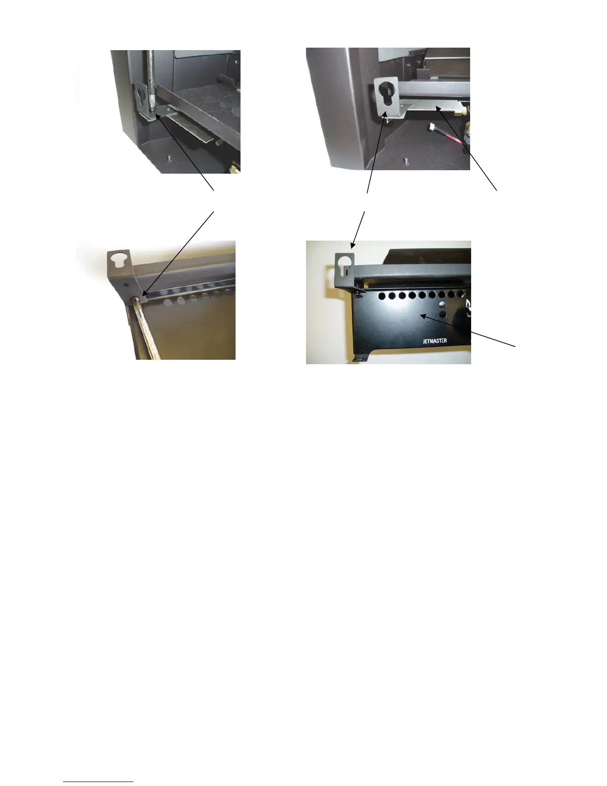
To fit the horizontal front locate the head of the screw attached to the rear of the front into the brack-
ets which have key hole shaped holes. Adjust screw length as applicable.
Remote Control - Handset and Sensor Mounting
The Remote Control handset generates an infrared signal, which will be received by the sensor situ-
ated at the front of the fire. This infrared signal requires a direct line of sight from the handset to the
sensor at the fire to ensure correct operation.
The range of operation with the remote control handset can be up to 6m. It is not permissible to
extend the range beyond this. The handset will not interfere with other remote devices as the fire
control system operates on a dedicated frequency.
Unpack the Remote Control Handset and install the 9v alkaline battery.
1. Remove the rear cover of the handset by pushing the clip and lifting the cover off.
2. Locate the connector ensuing battery terminal correct and press onto battery studs.
3. Replace rear cover ensuring cover clip secured.
Positioning the Sensor
Mounting the sensor in the correct position is critical for the fire to operate.
The object is to mount the sensor as unobtrusive as possible yet still have sufficient direct line of
sight to the handset to ensure correct operation every time. There is no one correct position to
mount the sensor as it will depend on the fire front fitted, the room and the type of installation.
Supplied is a plastic P clip and heavy duty double sided tape allowing for a multitude of mounting
positions to be achieved. The P clip can be used to mount the sensor to the ash pan cover or
hearth. The double sided tape can be used to mount the sensor to the ash pan cover, fire front or
the frame of the fire box.
Fig. 7c
Fig. 7a Fig. 7b
Fig. 7d
Fixing bracket
Heat shield
Self tap screw
Front plate
Manual Burner
RC Burner
 Loading...