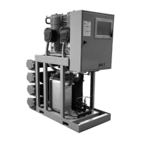
Jetson
www.JetsonHVAC.com
10
Model Number Descriptions
Digits 1 to 4— Model
FWCD
Digits 5 to 7 — Nominal
Capacity
020 = 20 Nominal Tons
030 = 30 Nominal Tons
045 = 45 Nominal Tons
055 = 55 Nominal Tons
065 = 65 Nominal Tons
075 = 75 Nominal Tons
085 = 85 Nominal Tons
Digit 8 — Unit Voltage
A = 208 V/60 Hz/3 Phase
B = 230 V/60 Hz/3 Phase
F = 460 V/60 Hz/3 Phase
G = 575 V/60 Hz/3 Phase
Digits 9 — Unit Application
A = Water-Cooled Chiller
B = Compressor Chiller with
Remote Condenser (40°F to
115°F)
D = Compressor Chiller with
Remote Condenser (20°F)
Digit 10 — Refrigeration Style
A = R-410A Scroll
Digit 11 — Number of Circuits
1 = Single Circuit
2 = Dual Circuit
Digit 12 — Efficiency/Capacity
1 = Standard Efficiency
2 = High-Capacity Evaporator
(allows 40F leaving water)
Digit 13 — Design Sequence
0 = Factory Assigned
Digit 14 — Array System
0 = Non-Array System
1 = Array System
Digit 15 — Evaporator Heat
Exchanger Type
0 = Brazed Plate
Digit 16 — Evaporator Fluid
Type
0 = Water
2 = Ethylene Glycol
3 = Propylene Glycol
Digit 17 — Evaporator Flow
0 = Constant Flow Primary
1 = Variable Flow Primary
Digit 18 — Evaporator
Temperature Range
0 = Standard Cooling
40 to 65°F [5.5 to 18.3°C]
1 = Standard Cooling/Ice Making
20 to 65°F [-6.7 to 18.3°C]
Digit 19 — Evaporator Control
Valves
0 = Manual Balancing Isolating
Valves
1 = Motorized Chilled Water
Isolating Valve
2 = No Valves (Standalone
Chiller)
Digit 20 — Condenser Heat
Exchanger Type
0 = Brazed Plate
1 = Shell and Tube
5 = Remote Condenser
Digit 21— Condenser Fluid
Type
0 = Water
2 = Ethylene Glycol
3 = Propylene Glycol
9 = Not Applicable —
Compressor-Chiller
Digit 22 — Condenser Heat
Recovery
0 = No Heat Recovery
1 = Heat Recovery
Digit 23 — Condenser
Corrosion Resistance
0 = Standard
1 = Cupro-Nickel (Avail. Shell
and Tube Only)
Digit 24 — Condenser Control
Valves
1 = Manual Valve
2 = Motorized Head Pressure
Control Valve
3 = No Valves (Standalone
Chiller)
Digit 25 — Power Feed
0 = Single Point Power (5 kA
Rating)
A = Single Point Power (5 kA
Rating) + Phase and Voltage
Monitor
B = Single Point Power (100 kA
Rating)
C = Single Point Power (100 kA
Rating) + Phase and Voltage
Monitor
D = Power Feed to Each Unit (5
kA Rating)
E = Power Feed to Each Unit (5
kA Rating) + Phase and Voltage
Monitor
F = Power Feed to Each Unit (100
kA Rating)
G = Power Feed to Each Unit
(100 kA Rating) + Phase and
Voltage Monitor
Digit 26 — Power Connection
0 = Terminal Block
A = Non-Fused Disconnect Switch
B = Fused Disconnect Switch
C = High SCCR Fuse Block
D = Distribution Panel
Connection = Terminal Block;
Module Power Connection =
Circuit Breaker
Digit 27 — Service Options
0 = None
A = LED Lighted Control Cabinet
Digit 28 — Panel Ampere
Rating
0 = None
D = 250 Amp
E = 400 Amp
F = 600 Amp
G = 800 Amp
H = 1200 Amp
Digit 29 — Control Style
0 = Master Secondary Controller
w/ Single Controller per Array
A = Supervisory Array Controller
w/ Controller per Module
B = Non-Array, Single Unit
Controller
Digit 30 — Local Unit
Controller Interface
0 = Keypad with Dot Pixel
Display
B = 15.4-in. Color Touchscreen
Digit 31 — Remote BMS
Interface (Digital Comm)
0 = None
2 = Lon Talk®
4 = BACnet® MS/TP
5 = BACnet® IP
6 = MODBUS®
8 = Johnson N2
Digit 32 — Blank
0 = Blank
Digit 33 — Blank
0 = Blank
Digit 34 — Refrigeration
Options
1 = Active Freeze Protection (All
Circuits)
2 = Hot Gas Bypass (All Circuits)
 Loading...