TEC1100 Series Thermostat Technical Bulletin 11
Remote
Clock/Timer
(if used)
Remote
Sensor
(if used)
Equipment
T1 T2
Field Contact Switches
Electronics
N2+
REF
N2-
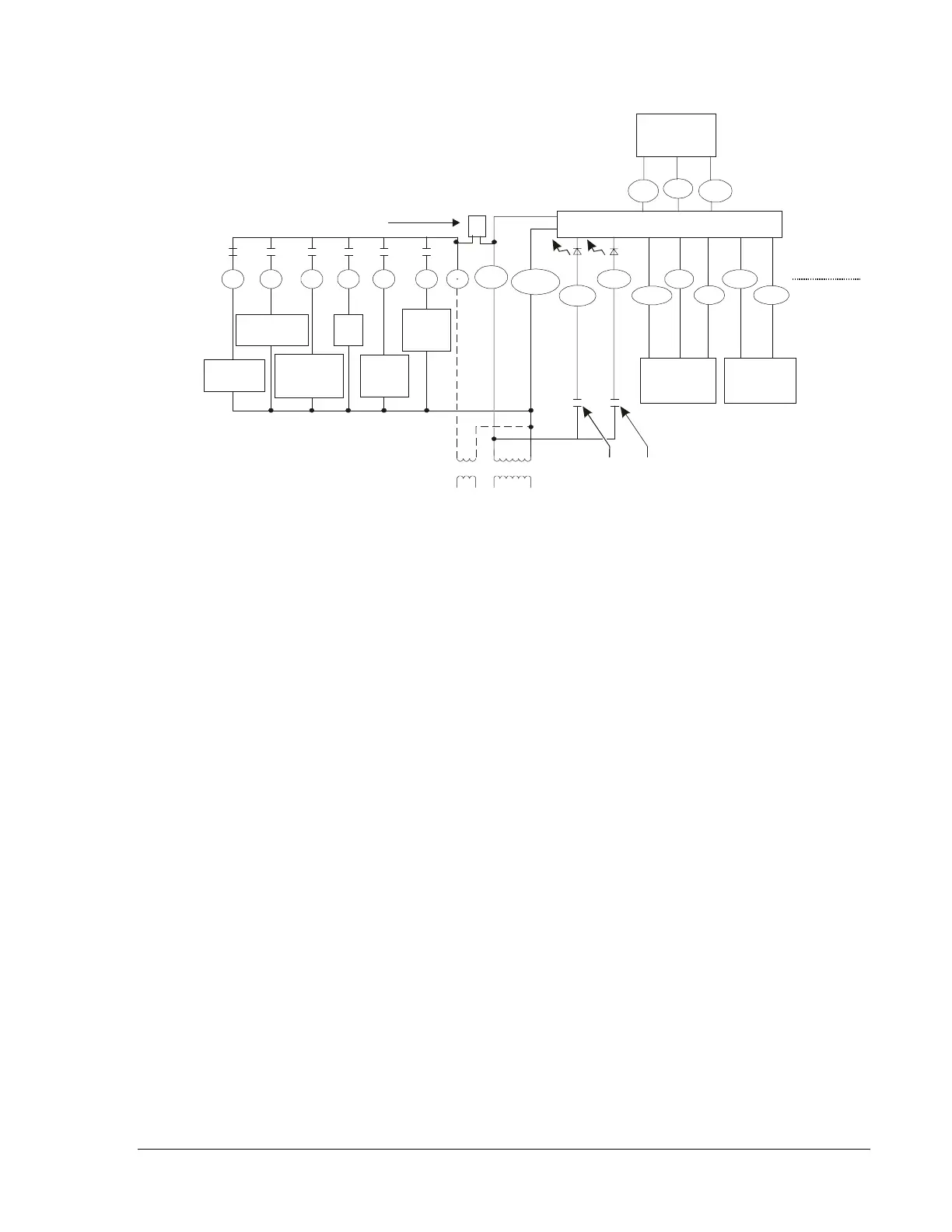
If the transformer (T2) is to power all of the loads, the
yellow pin jumper must be inserted connecting
R to 24 V. The jumper is located on the electronics board
above the relays. If a separate 24 V transformer (T1) is to
be used, it must be connected between R and 24 V(c), and
the jumper should be removed between R and 24 V.
Metasys
NCM
CPN, FAC,
Y1 Y2 G O B R CLK1
CLK2
24 V(c)
RS+V
RS1
RS2
LED2
24 V
Reverse
Valve
Heating
Reverse
Valve
Cooling
Fan
First Stage
Compressor
Hpndiag
LED1
W1
Jumper
Auxiliary
Heat
Thermostat
Second
Stage
Compressor
Figure 6: TEC1102 Heat Pump Wiring Schematic
 Loading...