12 TEC1100 Series Thermostat Technical Bulletin
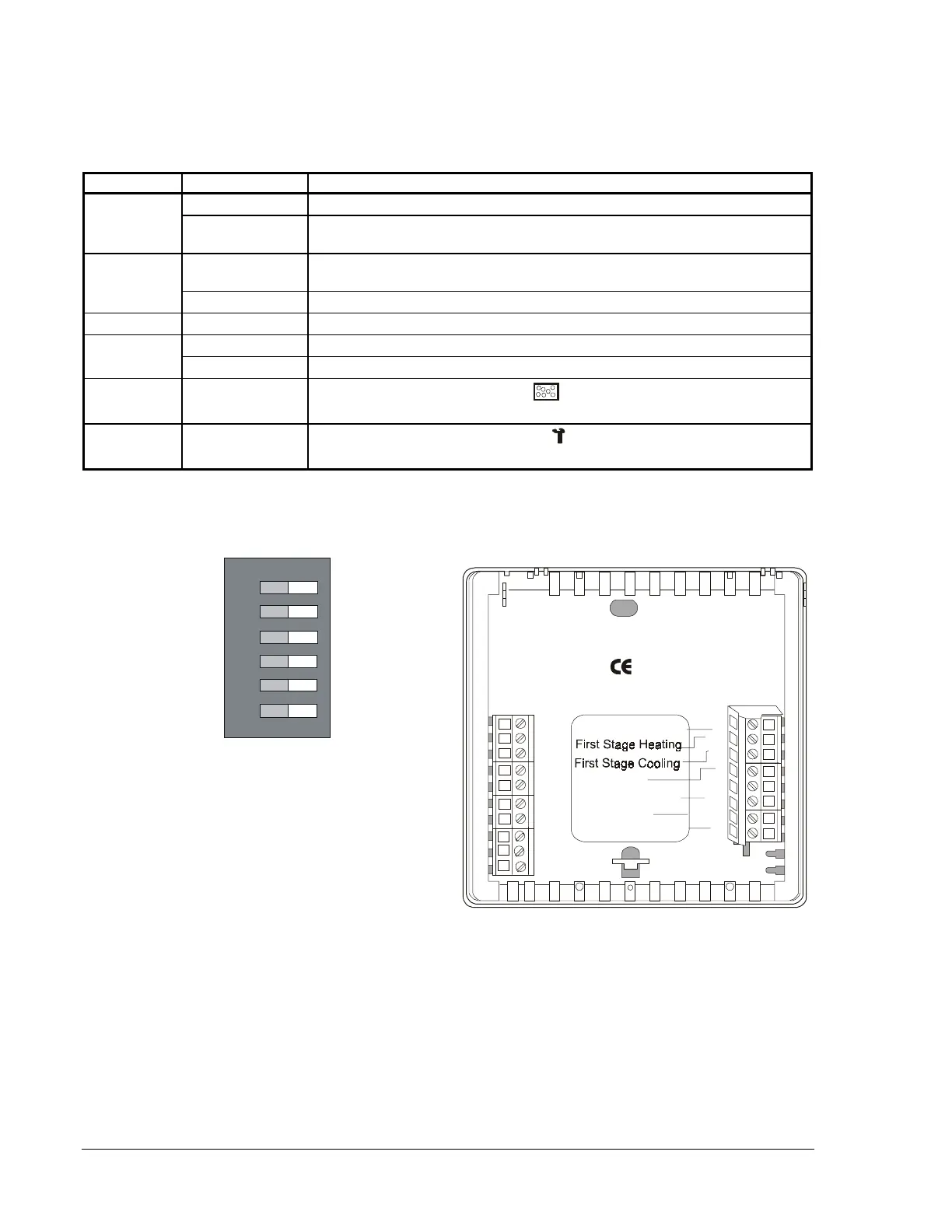
TEC1103 Multistage Wiring Configuration and DIP Switch Settings
Table 9: TEC1103 Multistage DIP Switch Selections
DIP Switch Selection Description
1
On Allows 2-minute minimum On/Off time for heating or cooling equipment.
Off Allows 4-minute minimum On/Off time for heating or cooling equipment
(preferred).
2
On*
Locks the keyboard, disabling buttons to prevent tampering. The Day/Night
mode button can select 1-hour override.
Off Unlocks the keyboard.
3
Off Not used. Switch should remain in the Off position.
4
On Allows multistage heating or cooling.
Off Allows single-stage heating or cooling.
5
LED 1 Icon
On/Off
Optional selection: LCD filter icon (
) comes on with LED 1 contact closure
to 24 VAC.
6
LED 2 Icon
On/Off
Optional selection: LCD wrench icon (
) comes on with LED 2 contact
closure to 24 VAC.
* When DIP Switch 2 is on, you can only use the Day/Night mode button to select 1-hour override to occupied
setpoints if in Night mode. All other buttons are read-only. You can also view the N2 address.
TEC1103
LED1
LED2
CLK1
Fan
Common
Msn2wire
N2+
N2-
REF
Heat/Cool: 2 Minute
(Minimum On/Off)
Keyboard Unlocked
Not Used
Single-Stage
LED 1 Icon Off
LED 2 Icon Off
Not Used
Multistage
LED 1 Icon
(Filter)
LED 2 Icon
(Wrench/Fault)
ON
1
3
2
4
5
6
Keyboard Locked
Heat/Cool: 4 Minute
(Minimum On/Off)
24 VAC Power In
RS2
RS+V
CLK2
Rs1
Y2
W1
Y1
G
R
24V
24V(c)
W2
Second Stage Cooling
Second Stage Heating
Figure 7: TEC1103 Multistage Factory-Set DIP Switch Setting and
Wiring Configuration
 Loading...