TEC1100 Series Thermostat Technical Bulletin 13
Table 10: TEC1103 Multistage Output Terminal Designations
Terminal Function
W2
Energizes on call for second stage heat.
Y2
Energizes on call for second stage cooling.
W1
Energizes on call for first stage heat.
Y1
Energizes on call for first stage cooling.
G Energizes fan on call for heating or cooling or by pressing the Fan button.
R
Independent switching voltage
24V
24 VAC from equipment transformer
24V(c)
24 VAC (common) from equipment transformer
LED 1, LED 2
Input connection that energizes LED 1 or LED 2 from remote status device to 24 VAC
CLK1, CLK2
Connections for remote clock/timer for alternate setpoints
RS2, RS1, RS+V
Connection for outdoor temperature sensor and/or indoor remote sensor option; refer to
instructions included with sensors.
N2+, N2-, REF
Metasys N2 Bus connections
Remote
Clock/Timer
(if used)
Remote
Sensor
(if used)
Thermostat
Equipment
T1
T2
Field Contact Switches
Second
Stage
Compressor
Electronics
N2+ REF
N2-
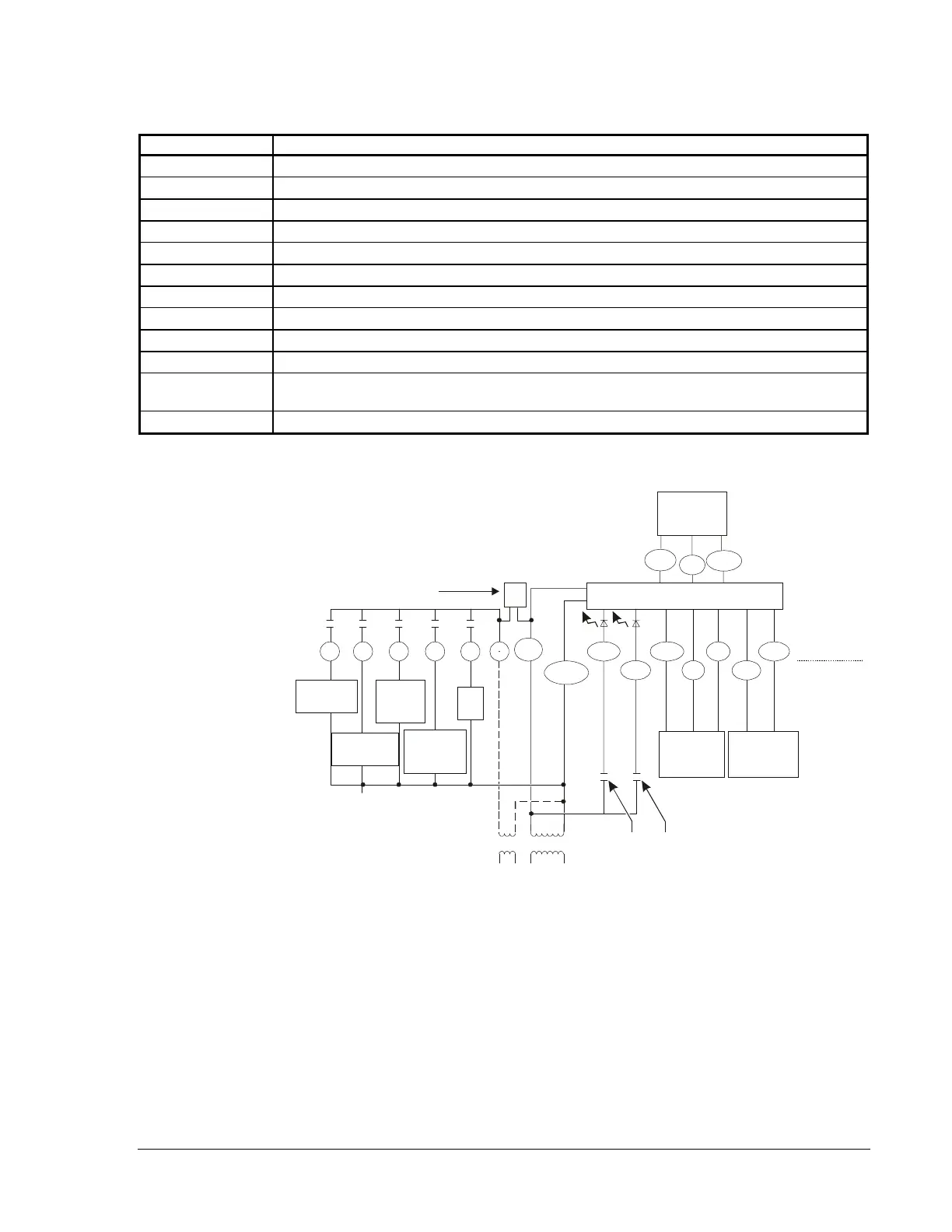
If the transformer (T2) is to power all of the loads, the
yellow pin jumper must be inserted, which connects
R to 24 V. The jumper is located on the electronics
board above the relays. If a separate 24 V transformer
(T1) is to be used, it must be connected between
R and 24 V(c), and the jumper should not be
connected between R and 24 V.
Metasys
NCM
CPN, FAC,
Y1
Y2
G
R
CLK1
CLK2
24 V(c)
RS+V
RS1
RS2
LED2
24 V
Fan
First Stage
Compressor
Second
Stage
Heat
Msndiag
LED1
W2
First Stage
Heat
W1
Jumper
Figure 8: TEC1103 Multistage Wiring Schematic
To connect the N2 Bus:
1.
Observe the polarity when connecting the N2 Bus wires to the
TEC1100.
Note: Each TEC has self-terminating End-of-Line (EOL) resistors.
However, one EOL resistor is needed at the BAS (two are
preferred at opposite ends).
2.
Continue this process for each TEC1100 using the daisy-chain wiring
method (Figure 9).
Connecting the
N2 Bus
 Loading...