TEC3000 Series Single- or Two-Stage Economizer Thermostat Controllers Installation Instructions
6
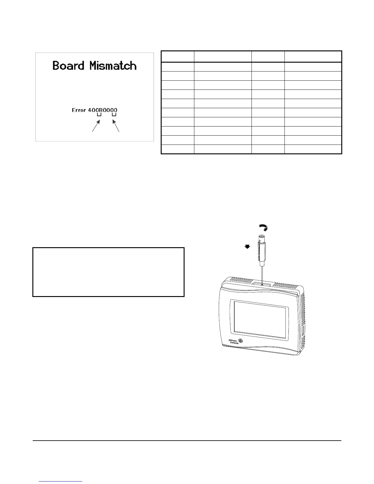
6. Use a 1/16 in. (1.5 mm) Allen wrench or
Johnson Controls T-4000-119 Allen-Head Adjustment
Tool (order separately) to reinstall the security screw
on the top of the thermostat controller cover.
7. Remove the protective plastic cover sheet from the
display.
Table 1: TEC3000 Model Names and Code Numbers
Name
Code Number
1
1. The two-character code number is listed within the error code to
indicate that the CPU board and base board do not belong together.
However, if the same code number appears as both the CPU board
and base board, there is no error. For example, if 0B is listed as the
CPU board and the base board, the model is the TEC3611.
Name
Code Number
1
TEC3310 00 TEC3610 0A
TEC3311 01 TEC3611 0B
TEC3312 02 TEC3612 0C
TEC3313 03 TEC3613 0D
TEC3320 04 TEC3620 0E
TEC3321 05 TEC3621 0F
TEC3322 06 TEC3622 10
TEC3323 07 TEC3623 11
TEC3330 08 TEC3630 12
TEC3331 09 TEC3631 13
IMPORTANT: If the display is dirty, gently wipe it
clean with isopropyl alcohol or ethyl alcohol. Do not
scrub hard as to avoid damaging the surface. Do not
use other cleaners such as water, ketones, and
aromatic solvents, since they may damage the
polarizer.
CPU Board
Base Board
Figure 5: Error Code Indicating
Mismatched Boards
Figure 6: Installing the Security Screw from the
Thermostat Controller Cover
(Shown without Occupancy Sensor)
 Loading...