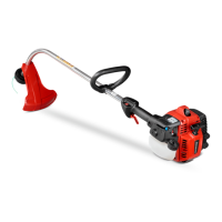
Tap Button
Trimmer
Head
S
Pull spool out of the trimmer head.
S
Clean dirt and debris from all parts.
S
Replace with a pre-wound spool , or re-
place line using 40 feet of 0.080
!
(2 mm)
diameter line.
S
When installing new line on an existing spool,
insert 1/16
!
of the line into the anchoring hole
in the bed of the spool, and wrap the line
evenly and and firmly around the spool in the
direction of the arr ow found on the spool.
Anchoring
Hole
S
Insert the end of the line through the exit hole
in the side of the trimm er head.
NOTE:
A metal insert is located in the exit
hole. As your unit wears from use, you can re-
install this insert upside down to provide a
new surface for the exit of the line from the
trimmer head.
WARNING:
When ins tallin g the metal
insert, you must install from the inside of the
trimmer head. If installed on the outside of the
trimmer head, this insert can fly off and become
a dangerous missile.
Metal Insert
S
Once line is passed through the exit hole,
place spool in the tr imm er head. Press the
spool down and turn the spool until it locks
down and does not pop up when you release
the spool.
S
Make sure the line is not caught between
the rim of the spool and the wall of the trim-
mer head.
S
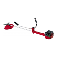
Replace the tap button, and place the lock
ring onto the trimmer head.
S
Align the lock ring over the catches on the
trimmer head. Push the ring down and tur n
until catches lock into place.
Catch
Catch
Catch
Catch
Lock
Tab
S
Make sure the lock ring is securely fas-
tened by pulling on it and twisting in both di-
rections.
WARNING:
All catches must be fas-
tened and lock tab latched in the lock ring. If
installed incorrectly, lock ring can fly off and be-
come a danger ous missile.
S
Pull the line extending from the trimmer
head. This will allow the spool to release
from the locked position.
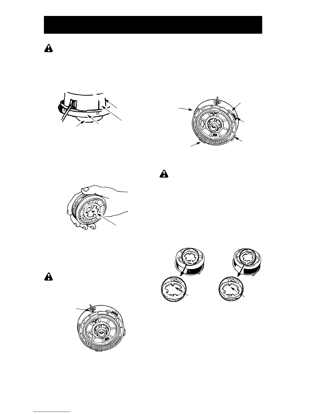
SPOOL REPLACEMENT
S
Replace the spool when the squar e cor ners
on the lugs are rounded off, r educed in size,
or broken. Follow instructions under LINE
REPL ACEMEN T for removing and installing
the spool.
Worn
Lug
Normal lug
BLADE REPLACEMENT
Refer to the ASSEMBLY section for blade re-
placement instructions and illustrations.
CARBURETOR ADJUSTMENT
Your carburetor is equipped with limiter caps.
Damage will occur if you turn the needles be-
yond the limiter stops. Carburetor adjustment
is a complicated task. We recommend that
you take your unit to an authorized service
dealer.
 Loading...