6
CAUTION:
Do not overtighten screw .
There must be at least 1/8” free play in the trig-
ger. Make sure trigger will move freely so the
engine can fully return to idle when the trigger
is released.
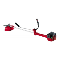
ATTACHING THE HANDLEBAR
DANGER:
During blade usage, the
barrier portion of the handlebar must be
installed as shown to provide a barrier be-
tween operator and the spinning blade.
S
Locate the decal on the handlebar. This
decal includes two arrows. Position the
handlebar with the mounting bracket
between these arrows.
S
Position the bracket cover over the
handlebar. Again make sure the handlebar
is between the arrows.
S
Insert screws and hand tighten only. Be
sure the handlebar is installed correctly;
then, tighten each screw securely with the
short hex wrench.
Bracket Cover
Screw
Mounting
Bracket
Handlebar
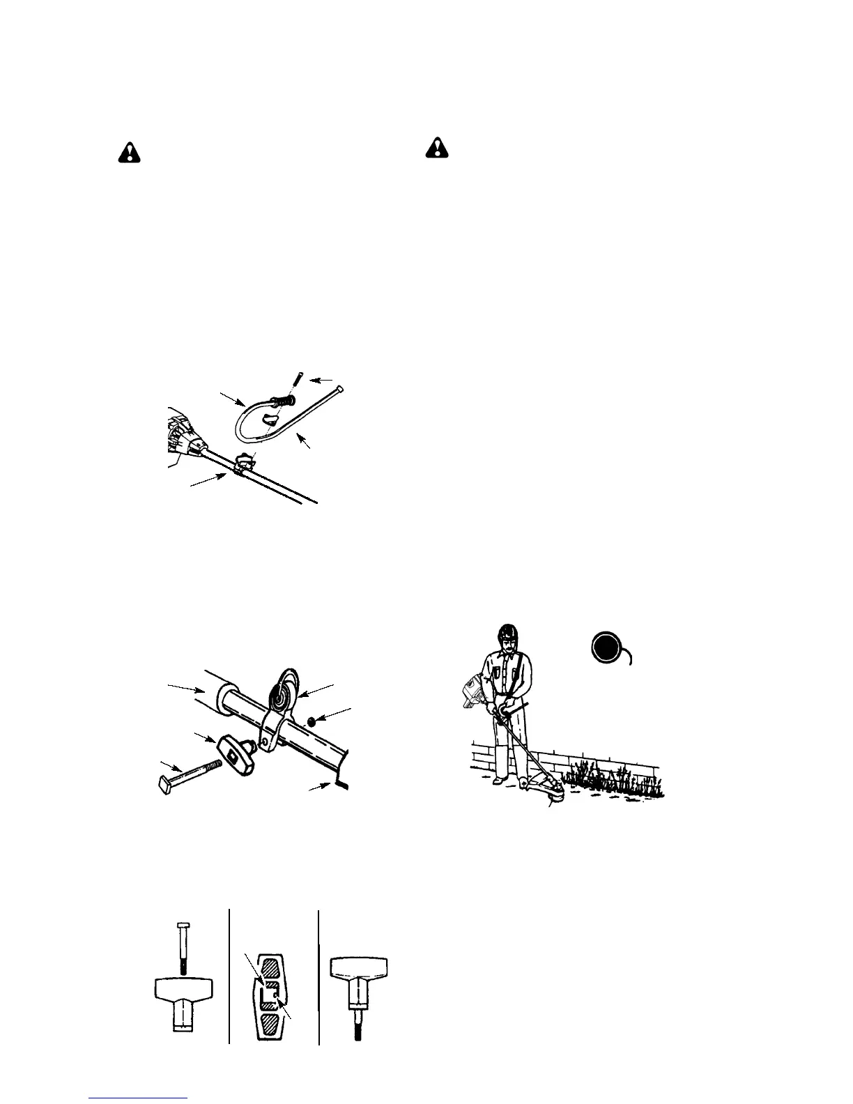
ASSEMBLY OF SHOULDER STRAP
1. Align shoulder strap clamp between han-
dlebar mounting bracket and engine.
2. Firmly push the shoulder strap clamp
onto the tube. Be sure that the shoulder
strap clamp is installed with the hex
shaped recession (on the clamp) facing
the left side of the tube as viewed from the
engine.
Throttle Grip
Shoulder Strap
Clamp
T--handle
Nut
Handlebar
Mounting Bracket
Screw
3. Drop the threaded end of the screw
through the opening in the top of the T--
handle.
4. Pull on the threaded end of the screw to
bring the head of the scrw past the tab in-
side the T--handle.
Before Assembly
Top View Assembled
Screw
T--handle
Square Head
Screw Seated
Tab
5. Seat nut in the hex shaped recession on
the back side of the shoulder strap clamp.
6. Insert the threaded end of the screw
through the hole in the shoulder strap
clamp and tighten securely by hand
only.
WARNING:
Proper shoulder strap
and handlebar adjustments are requir ed before
starting the engine.
7. T r y on shoulder str ap and adjust for fit and
balance before starting the engine or begin-
ning a cutting operation.
8. Insert your right arm and head through
the shoulder strap and allow it to rest on
your left shoulder. Make sure the danger
sign is on your back and the hook is to the
right side of your waist.
NOTE:
A one-half twist is built in the shoulder
strap to allow the strap to rest flat on the
shoulder.
9. Adjust the strap, allowing the hook to be
about 150 mm below the waist.
10. Fasten the str ap hook to the clamp located
between the trigger handle and the handle-
bar clamp base and lift the tool to the oper-
ating position.
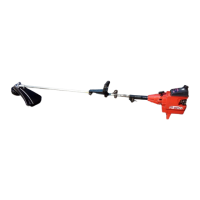
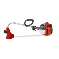
CONFIGURING YOUR UNIT
You can configure your unit using a cutting
head for grass and light weeds, or a weed
blade for cutting grass, weeds, and brush up
to 13 mm in diameter. To assemble your unit,
go to the section for the desired configuration
and follow the instructions.
ASSEMBLY INFORMATION --
TRIMMER HEAD
TRIMMER
HEAD
NOTE:
Remove the blade and metal shield
before attaching the plastic shield and trimm er
head. To remove blade, push in locking lever
and hold. Rotate blade nut until the locking lever
falls into one of the grooves in the dust cup.
Continue to hold the locking lever. This will keep
the shaft from turning while loosening the blade
nut. Remove blade nut by turning clockwise.
Release locking lever. Remove both washers
and blade. To remove metal shield, loosen and
remove the four mounting screw s. See A T-
TAC HING THE METAL SH IELD and INSTAL-
LATIO N OF TH E METAL BLADE for illus tr a-
tions. Be sure to store all parts and instructions
for futur e use.
 Loading...