5
ASSEMBLY
CARTON CONTENTS
Check carton contents against the following list:
S
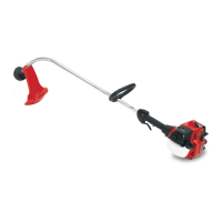
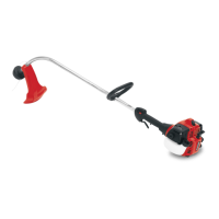
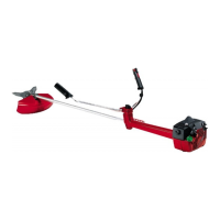
Brushcutter
S
Blade shield screws (4)
S
Cupped washer
S
Large nut for installing blades
S
Hex wrench
S
Metal shield
S
Plastic shield
S
Shoulder strap with warning
S
4--point weed blade
S
Trimmer head
S
Handlebar
S
Wing nut
WARNING:
Always stop unit and dis-
connect spark plug before performing any as-
sembly procedures.
WARNING:
If received assembled,
repeat all steps to ensure your unit is properly
assembled and all fasteners are secure.
Examine parts for damage. Do not use dam-
aged parts.
It is normal for the fuel filter to rattle in the
empty fuel tank.
Finding fuel or oil residue on muffler is normal
due to carburetor adjustments and testing
done by the manufacturer.
TOOLS REQUIRED
S
Hex wrench (provided)
S
Adjustable wrench
ATTACH THE TUBE
NOTE:
Illustrations within this sectio n w ill help
in identifying the assembly steps. Be sure to
re a d each section and revie w the illustr a tion s ,
before you begin.
NOTE:
A drive shaft is located in the center of
the tube. Make sure this shaft does not fall out of
the tube. Dirt on the shaft will significantly re-
duce the life of the unit. If this shaft falls out,
clean, relubr icate , and re-install.
S
Insert the 2 tube assembly screws and nuts
as illustrated. Keep loose at t his time, you
will tighten them during a later step.
S
Position locknuts in lower holes.
S
Tighten the screws with the hex wrench just
enough to hold the hardware together while
holding the locknuts with your other hand.
S
Remove the packing cover from the
straight end of the tube (your unit may not
have a packing cover.)
S
Pull about 1/2 inch of the drive shaft out of
the inside of the tube.
Drive shaft
Tube
NOTE:
The end of the drive shaft is square.
This square end fits inside a square hole in a
shaft inside the engine. Look inside the end of
the engine and you will see the square hole in
the sh a ft.
NOTE:
The end of the tube has a groove that
aligns with a ridge in the engine opening. Lo-
cate the groove and ridge.
GrooveRidge
S
Align the groove in the tube with the ridge in
the engine opening. Insert the tube into the
opening.
S
Firmly push the tube into engine until it will no
longer go into the opening.
S
Tighten screws alternately with the hex
wrench until secure.
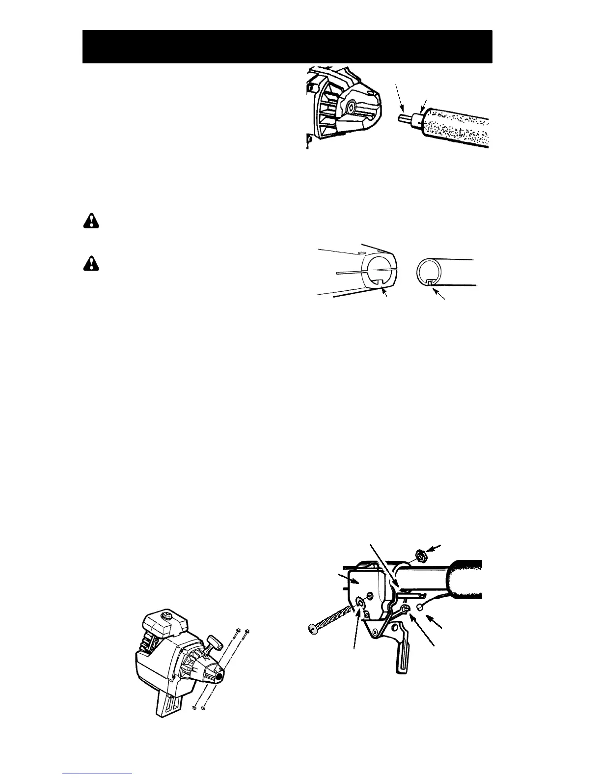
ATTACH THE THROTTLE CABLE
CAUTION:
Do not bend the throttle cable.
S
Slide the throttle trigger housing from the
foam grip about 1
!
to 1--1/2
!
.
S
Insert the throttle cable through the tunnel in
the foam grip until the end of the cable ex-
tends at least 2 inches beyond grip.
S
Hold the trigger away from the tube; insert
the barrel end of the throttle cable into the
round opening in the trigger.
NOTE:
When inserting barrel end of the
throttle cable into the round opening in trigger,
make sure that the barrel is completely in-
serted and throttle cable is located in the split
in the arm.
Screw
Nut
Arm
Barrel
Round hole in
trigger
Throttle
trigger
housing
Foam grip
Lockwasher
S
Push the cable back into the split in the arm.
Guide the arm into the foam grip tunnel until
the throttle trigger housing is flush against
the grip.
S
Squeeze and hold trigger against foam grip.
Install screw and nut.
 Loading...