- 9 -
6. Connecting the Power Code
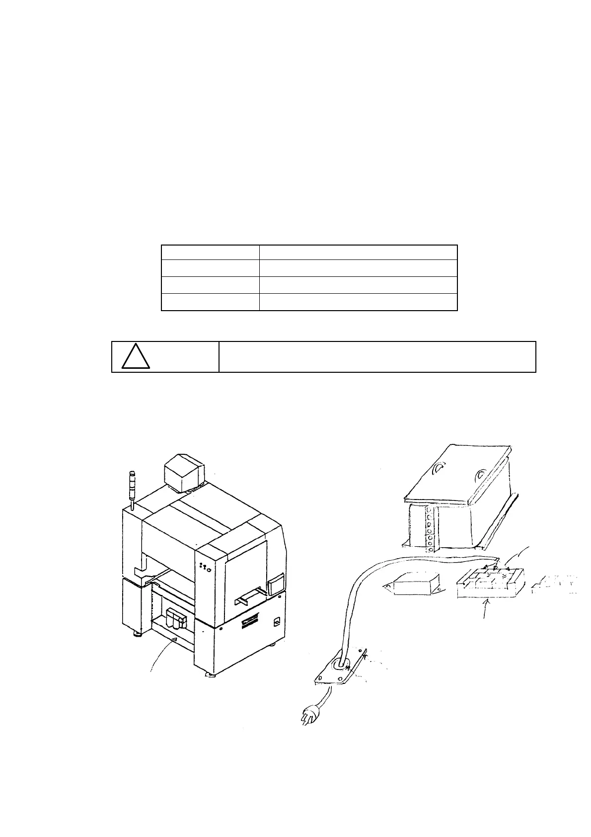
(1) Remove the cover RBC located on the rear of the main unit.
(2) Insert the power code inside the main unit via a groummet with a film after passing it
through a mouth guard as shown in Figure 6.2.
2-1 Be sure to install the insulation cover on the terminal plate after connecting the
power code to the terminal plate.
(3) Connect each terminal of the power code to the terminal plate of the power unit.
3-1 You can connect the black line to the No. 2 plate and the white line to the No. 1
plate because the alternate current is supplied.
Table 6.1
Color of the line Number of the terminal plate
Black (white 1
White (black) 2
Green 3
Make sure that the plugs of the power supply side has been
assembled before connecting the power code to the main unit.
CAUTION
!
Figure 6.2
Ground
Figure 6.1 Main unit (rear side)
Cover RBC
Grommet with a film
Mouth guard
Terminal plate