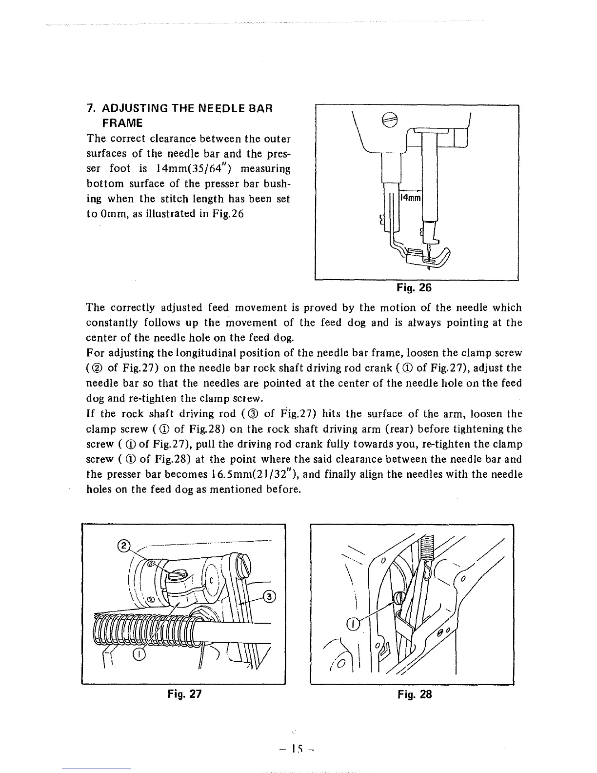
7.
ADJUSTING THE NEEDLE BAR
FRAME
The
correct clearance between
the
outer
surfaces
of
the needle bar and the pres-
ser
foot
is
14mm(35/64")
measuring
bottom
surface
of
the
presser bar bush-
ing when
the
stitch length has been set
to
Omm,
as
illustrated in Fig.26
Fig.
26
The correctly adjusted feed movement
is
proved by the motion
of
the
needle which
constantly follows
up
the
movement
of
the feed dog and
is
always pointing at
the
center
of
the needle hole on the feed dog.
For
adjusting
the
longitudinal position
of
the
needle
bar
frame, loosen
the
clamp screw
( ®
of
Fig.27) on
the
needle bar rock shaft driving rod crank
(CD
of
Fig.27), adjust the
needle bar so
that
the needles are pointed
at
the
center
of
the
needle hole
on
the
feed
dog and re-tighten the clamp screw.
If
the rock shaft driving
rod
( ®
of
Fig.27) hits
the
surface
of
the arm, loosen the
clamp screw
(CD
of
Fig.28)
on
the
rock shaft driving arm (rear) before tightening the
screw
(CD
of
Fig.27), pull the driving rod crank fully towards you, re-tighten
the
clamp
screw
(CD
of
Fig.28) at the point where
the
said clearance between
the
needle bar and
the
presser bar becomes
16.
5mm(21/32"),
and finally align
the
needles with
the
needle
holes on the feed dog as mentioned before.
Fig.
27
Fig.
28
-IS-
 Loading...