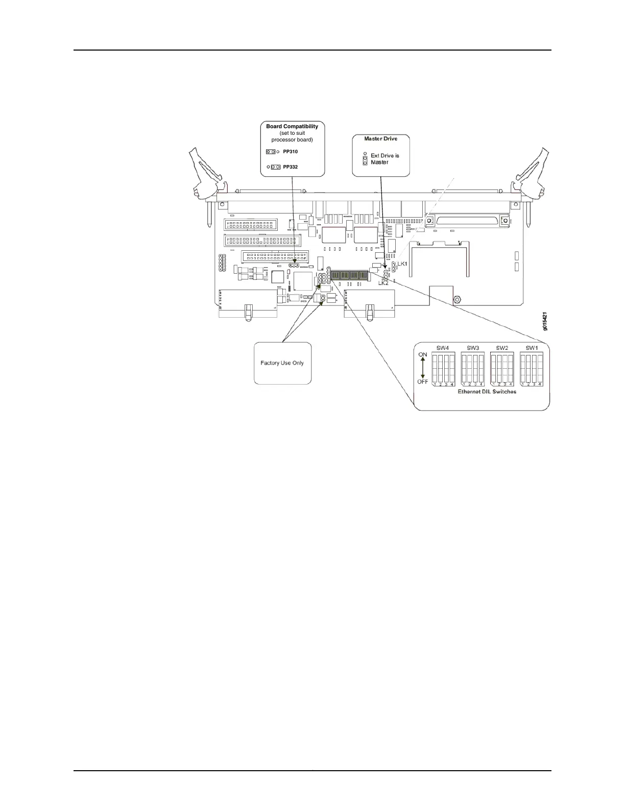
Figure 3: RTM Default Jumper Settings
PP310
PP332
Board Compatibility
(set to suit
processor board)
g015421
5. Confirm that Ethernet dip switches SW1 and SW2 are set to ON, and that SW3 and
SW 4 are set to OFF (see Figure 3 on page 12).
6. Install the 4-GB CompactFlash card from the upgrade kit in the new RTM and install
the new RTM in the chassis. See “Installing or Removing a CTP2000 Series
CompactFlash Card” on page 26.
7. Attach a terminal server or similar device to the serial console port, COM2, on the RTM.
This device will be used to interact with the script that runs when the upgrade
CompactFlash card is booted.
8. Remove the CPU card from the chassis, and replace the memory module on the CPU
card with that from the upgrade kit. Install the memory module shipped with the kit
only after you have finished these tasks. See “Installing or Replacing CTP2000 DRAM
Memory Modules in the PP310 or PP332 CPU” on page 23 and Upgrading CTP2000
Series Components for Memory Upgrades.
9. Reset the BIOS to factory defaults. See “Restoring BIOS Defaults for the CTPOS 7.0R1
and Later Upgrade (PP310)” on page 24.
10. Reconnect all Ethernet cables.
11. Replace the power cord.
12. Power on the system and follow the procedure “Using the Upgrade CompactFlash
Card” on page 14 to respond to the instructions that appear on the serial console. You
have the option of conserving information from a prior release of the operating system
or setting the device for firstboot with CTP0S 7.0R1 and later.
Copyright © 2015, Juniper Networks, Inc.12
Upgrading the CTP2000 Series Device to CTPOS 7.x

 Loading...