•
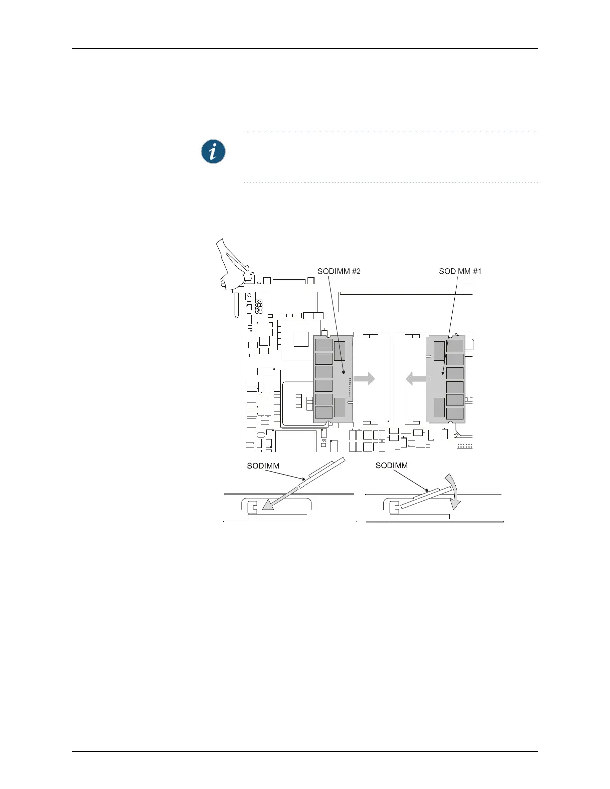
Release the memory module by using your thumb to raise the end of the memory
module to the angle shown in Figure 5 on page 24.
NOTE: Figure 5 on page 24 shows the PP310 CPU. The memory module
is removed and replaced in the same manner for the PP332 CPU.
•
Hold the memory module between your thumb and forefinger and gently pull it out
of the socket.
Figure 5: DRAM Memory Module Replacement — PP310
5. To insert the new memory module:
•
Hold the module between your thumb and forefinger and insert one end into the
socket at the angle shown in Figure 5 on page 24.
•
Lower the free end of the module until it snaps into place.
6. Return the CPU to the chassis and secure it in place. See “Servicing the CTP2000
CPU” on page 23.
Restoring BIOS Defaults for the CTPOS 7.0R1 and Later Upgrade (PP310)
You must restore default BIOS settings (stored in CMOS) during the CTPOS 7.0R1 upgrade
process for the PP310. Refer to Figure 6 on page 25 when performing the following
procedure.
Copyright © 2015, Juniper Networks, Inc.24
Upgrading the CTP2000 Series Device to CTPOS 7.x

 Loading...