EasyManua.ls Logo

JVC AX-R551BK User Manual

JVC AX-R551BK
66 pages
To Next Page IconTo Next Page
To Previous Page IconTo Previous Page
Page #4 background image
AX-R551
BK
FRONT
PANEL
{
=
-=
:
==
8 :
:
.=
.=
.=
.=
.=
AX-R551BK
o
REMOTE
SENSOR
.-~,....,-""""'~
.....
,..---.,""~-~
~"",,"""-'''''''O£T'BO~
-~"",,,,,,,,,,,,,,,,,,
.....
-
__
....
,_c.--....~
-'''-'''''''''''':'''"''-'ll''''''''~'''''-'-'''-'
.".
'->.<'
~
..
"'-
"""
..
,,"'..,
Th
is
sensor receives
infrared
signals
from
the
remote
control
unit.
RECEIVED
indicator
This
indicator
will
(10 on
while
infrared
signals are being
received from
the
remote
control
unit
f)
POWER
ON:
Press
to
turn
the
power
on
To
turn
the
power
off.
press
it
again.
STAND
BY:
When all
of
the
Indicators
(other
than
the
STAND
BY)
are
turned
off.
the
memory
circuit
operates
and
the
preset
stations
and
the
source selectors are
not
subject
to
cancellation
or
accidental
alteration
as
long
as
the
power
cord
is
plugged
into
an
AC
outlet.
This
situation
is
called
the
STAND
BY
mode.
The
preset data and
the
source
select data are
maintained
even in
the
case
of
a
power
failure
or
when
the
power
cord
is
disconnected.
provided
loss
of
power
does
not
exceed a
u)uple
of
days
STAND
BY
indicator
Connecting
the
power
plu~l
to
the
AC
wall
outlet
causes
this
indicator
to
light,
indicating
that
the
unit
has
been
placed
in
the
stand·by
mode.
The
light
of
this
indicator
will
go
out
when
the
power
button
is
turned
on
1-4 (No. 20016)
-7-
PANNEAU AVANT
MEM
ORV---0
MANUAL
---,
__
IPROGf.'lA~~
~
~A
~
B
~C
e
~
D
~
"
o Detecteur
de
telecommande
(REMOTE
SENSOR)
Fig.3
Fig.4
Ce
cJetecteur
recoit
les
signaux infrarouges
provenant
de
la
telecornmande.
Indicateur
de
reception
(RECEIVED)
Cet IrlClicateur
s'allume
quand
cles
signallx infrarDuge
provenant
cle
la
telecommande
sont
recus.
f}
Alimentation (POWER)
ON:
Appuyc3[
pour
mettre
I'alimentation.
Pour
couper
I'alimentation,
appuyer
line
nouvelle
fois.
STAND
BY:
Meme
quand
tous
les
indicateurs
(autres
que
I'indicateur
STAND
BY)
sont
eteints,
le
circuit
de
men
oire
fonctionne
et
les
stations
prereglees et
les
selecteur5 de
source ne
sont
pas
annules ou
modifies
par
acciclent1ant
que
le
cordon
(j'alimentation
est
branche
a une prise sec1eur
murale. Cet
etat
est appele
le
mode
ST
AN
D
BY
Les
informations
prereglees et
les
selections de source
sont
maintenues
meme
en
cas
cle
panne de
courant
ou
qua~
d le
cordon
d'al
imentation
est
debranche a
condition
qce
la
perlode
d'ahsence
d'alimentation
n'excede
pas
deux
10
urs.
Indicateur d'attente
(STAND
BY)
Le
fait
de
brancher
la
fiche
d'alimentation
a une
?rise
secteur
mllrale
entralne
I'allurnage
cle
cet
indlcat€ur,
signifiant
que
I'apparell a ete rnis
en
mode
attente. Cet
Inclicateur
s'etelnt
quand
I'intorrupteur
(j'alirnentation
est
rnis sllr
la
position
sous tension.

Table of Contents

Question and Answer IconNeed help?

Do you have a question about the JVC AX-R551BK and is the answer not in the manual?

JVC AX-R551BK Specifications

General IconGeneral
BrandJVC
ModelAX-R551BK
CategoryAmplifier
LanguageEnglish

Summary

Safety Precautions and Specifications

Safety Precautions and Warnings

Essential safety checks and general warnings for equipment operation and maintenance.

Detailed System Specifications

Output, input, signal, and general specifications of the audio system.

Front Panel Controls and Operation

Front Panel Layout and Indicators

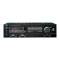
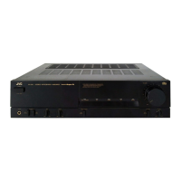
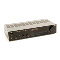
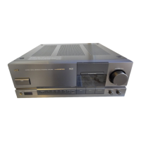
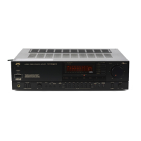
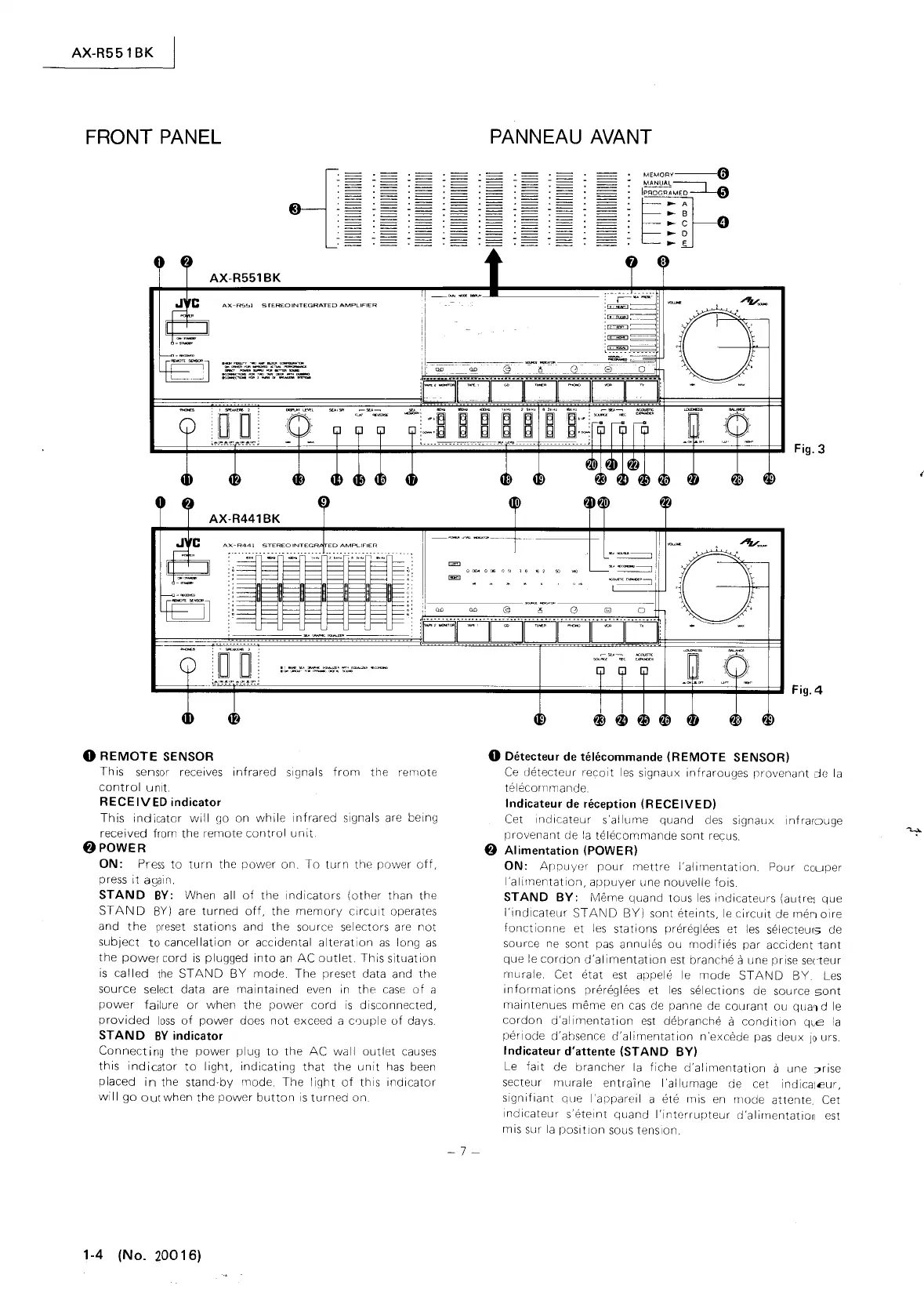
Explains all controls and indicators on the front panel.

Power and Standby Functions

Controls for turning the unit on/off and standby mode.

SEA Equalizer Controls and Indicators

Details SEA indicators, presets, and level adjustment controls.

Speaker, Headphone, and Source Selection

Controls for speakers, headphones, and audio input sources.

Special Function Controls (Volume, Balance, etc.)

Operation of Acoustic Expander, Loudness, Balance, and Volume controls.

Remote Control and COMPU LINK System Operation

Remote Control Unit Operation Guide

Detailed guide on using the remote control unit's functions.

COMPU LINK System Overview and Operation

Explanation of COMPU LINK system, source selection, and synchronized recording.

Audio Playback, Recording, and Special Features

Initial Setup and Broadcast Listening

Connecting components and tuning radio broadcasts.

Playback Procedures for Various Sources

Instructions for playing records, CDs, tapes, TV, and VCR.

Recording and Tape Dubbing Procedures

Steps for recording audio and dubbing tapes between decks.

SEA Equalizer Presets and Recording

Using SEA equalizer presets and recording with SEA effect.

CD Changer and Surround Control Operation

Operating the CD auto changer and surround processor.

Tape, VCR, DAT Control and Effects

Controlling COMPU LINK devices and applying special effects.

Audio/Video Signal Switching and Volume Control

Switching signals, adjusting volume, and muting sound.

Service Procedures and Technical Diagrams

Component Removal and Adjustment Procedures

Steps for disassembling the unit and performing internal adjustments.

LSI Explanation and IC Block Diagrams

Details of LSI, IC pin functions, and block diagrams.

Schematic Diagrams

Circuit diagrams for various sections of the audio system.

Parts Lists and Diagrams

Remote Control Unit Parts and Schematic

Schematic, parts list, and key layout for the remote control.

Connection and Block Diagrams

Diagrams showing component interconnections and system architecture.

Comprehensive Parts Lists by Section

Detailed lists of all parts organized by section and PCB.

Packing Materials and Accessories List

Information on packing materials and included accessories.

Related product manuals