1-16 (No.MB150)
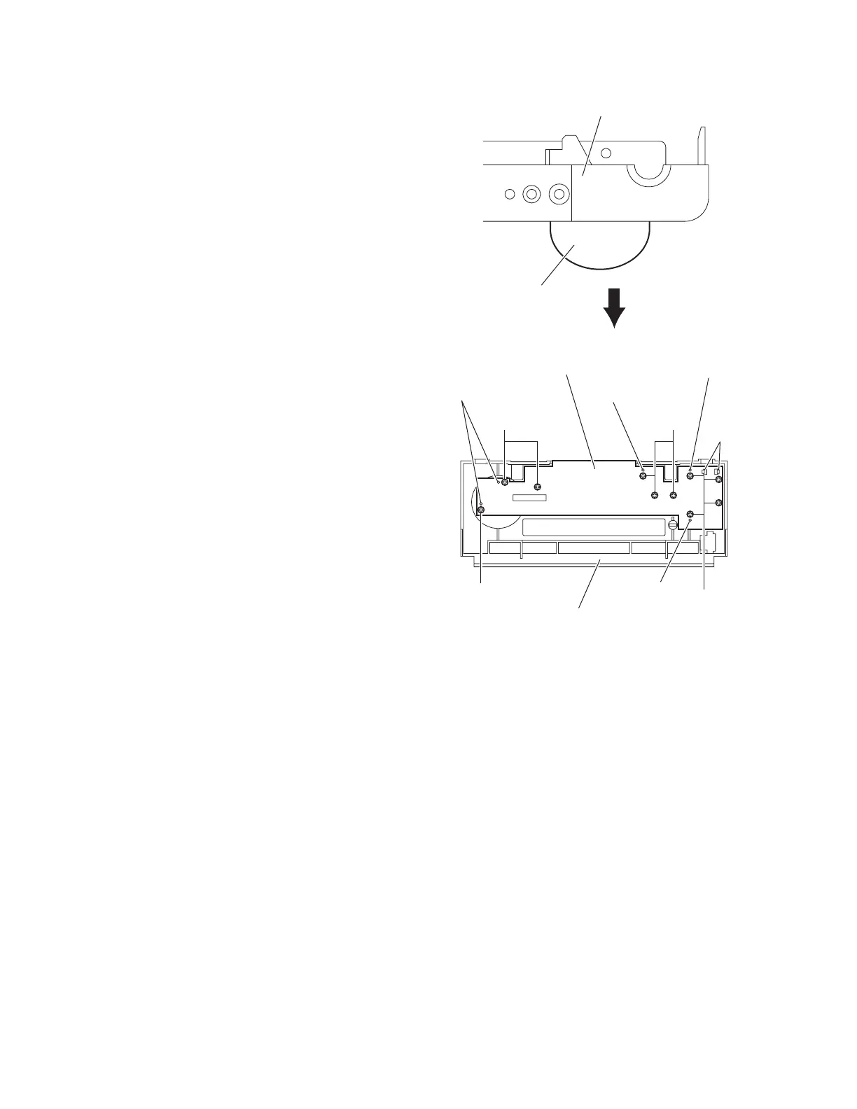
3.1.15 Removing the front board
(See Figs.25 and 26)
• Remove the top cover.
• Remove the AL panel L and AL panel R.
• Remove the front panel assembly.
(1) From the forward side of the front panel assembly, pull out
the volume assembly. (See Fig.25.)
(2) From the reverse side of the front panel assembly, remove
the ten screws AA attaching the front board. (See Fig.26.)
(3) Release the two claws aa of the indicator attaching the
front board and take out the front board from the front panel
assembly. (See Fig.26.)
Reference:
When attaching the front board, attach the screw AA after fit-
ting the hole of the front board to the projections ab of the front
panel assembly. (See Fig.26.)
Fig.25
Fig.26
Volume assembly
Front panel assembly
Projection ab
Front board
Front panel assembly
AA AA
AA
AA
Projection ab
Projection ab
Projections ab
Claws aa
 Loading...