(No.MB150)1-17
3.2 DVD mechanism section
• Remove the DVD mechanism assembly from the main body.
(See "3.1.13 Removing the DVD mechanism assembly".)
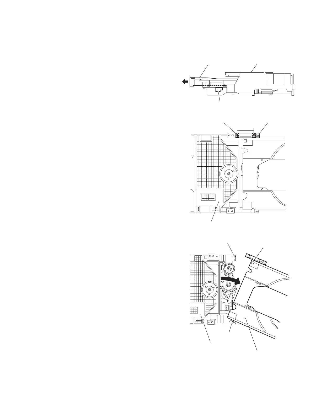
3.2.1 Removing the tray assembly
(See Figs.1 to 3)
(1) From the right side of the DVD mechanism assembly, push
the slide cam and pull the tray assembly out of the DVD
mechanism assembly in the direction of the arrow. (See
Fig.1.)
(2) From the top side of the DVD mechanism assembly,
remove the two screws A attaching the leaf spring to the
bushing and remove the leaf spring. (See Fig.2.)
(3) Remove the bushing of the tray assembly from the
projection a on the DVD mechanism assembly and move
the tray assembly in the direction of the arrow. (See Fig.3.)
(4) Remove the claw b of the tray assembly from the DVD
mechanism assembly and take out the tray assembly. (See
Fig.3.)
Fig.1
Fig.2
Fig.3
Tray assembly
DVD mechanism assembly
Slide cam
Bushing
Leaf spring
A
DVD mechanism assembly
Bushing
Claw b
Projection a
Tray assembly
DVD mechanism assembly
 Loading...