1-18 (No.MB150)
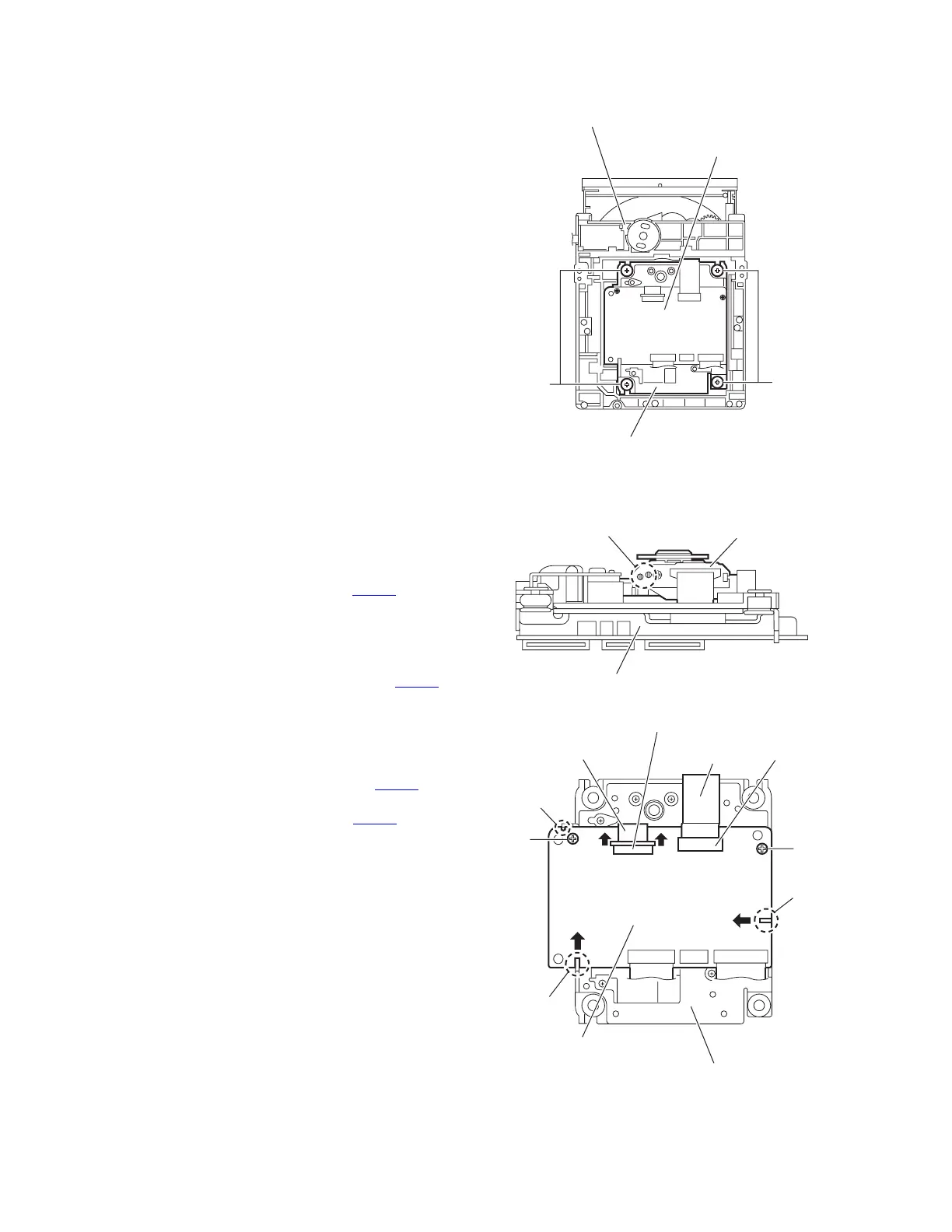
3.2.2 Removing the traverse mechanism assembly
(See Figs.4)
(1) From the bottom side of the DVD mechanism assembly,
remove the four screws B attaching the traverse
mechanism assembly and take out the DVD traverse
mechanism assembly with the DVD servo board.
Fig.4
3.2.3 Removing the DVD servo board
(See Figs.5 and 6)
• Remove the traverse mechanism assembly.
(1) From the side of the traverse mechanism assembly, solder
the short land sections c on the pickup. (See Fig.5.)
(2) From the bottom side of the traverse mechanism
assembly, release the lock of the connector CN101
on the
DVD servo board in the direction of the arrow 1 and
disconnect the card wire. (See Fig.6.)
Caution:
• Solder the short land sections c on the pickup before
disconnecting the card wire from the connector CN101
on the DVD servo board. If the card wire is
disconnected without attaching solder, the pickup may
be destroyed by static electricity. (See Figs.5 and 6.)
• When attaching the DVD servo board, be sure to
remove solders from the short land sections c after
connecting the card wire to the connector CN101
on
the DVD servo board. (See Figs.5 and 6.)
(3) Disconnect the card wire from the connector CN201
on the
DVD servo board. (See Fig.6.)
(4) Remove the two screws C attaching the DVD servo board.
(See Fig.6.)
(5) Remove the DVD servo board from the engagement
section d in an upward and remove the engagement
section f in the direction 3 while removing the engagement
section e in the direction of the arrow 2. (See Fig.6.)
Fig.5
Fig.6
DVD mechanism assembly
Traverse mechanism assembly
DVD servo board
B
B
Traverse mechanism assembly
Pickup
Short land section c
Card wire
Card wire
DVD servo board
Traverse mechanism assembly
CN101
CN201
1
1
2
3
C
C
f
e
d
 Loading...