(No.MB150)1-19
3.2.4 Removing the pickup
(See Figs.5,7 to 9)
• Remove the traverse mechanism assembly.
(1) From the side of the traverse mechanism assembly, solder
the short land sections c on the pickup. (See Fig.5.)
(2) Release the lock of the connector on the pickup in the
direction of the arrow and disconnect the card wire. (See
Fig.7.)
Caution:
• Solder the short land sections c on the pickup before
disconnecting the card wire from the connector on the
pickup. If the card wire is disconnected without
attaching solder, the pickup may be destroyed by
static electricity. (See Figs.5 and 7.)
• When attaching the pickup, be sure to remove solders
from the short land sections c after connecting the
card wire to the connector on the pickup. (See Figs.5
and 7.)
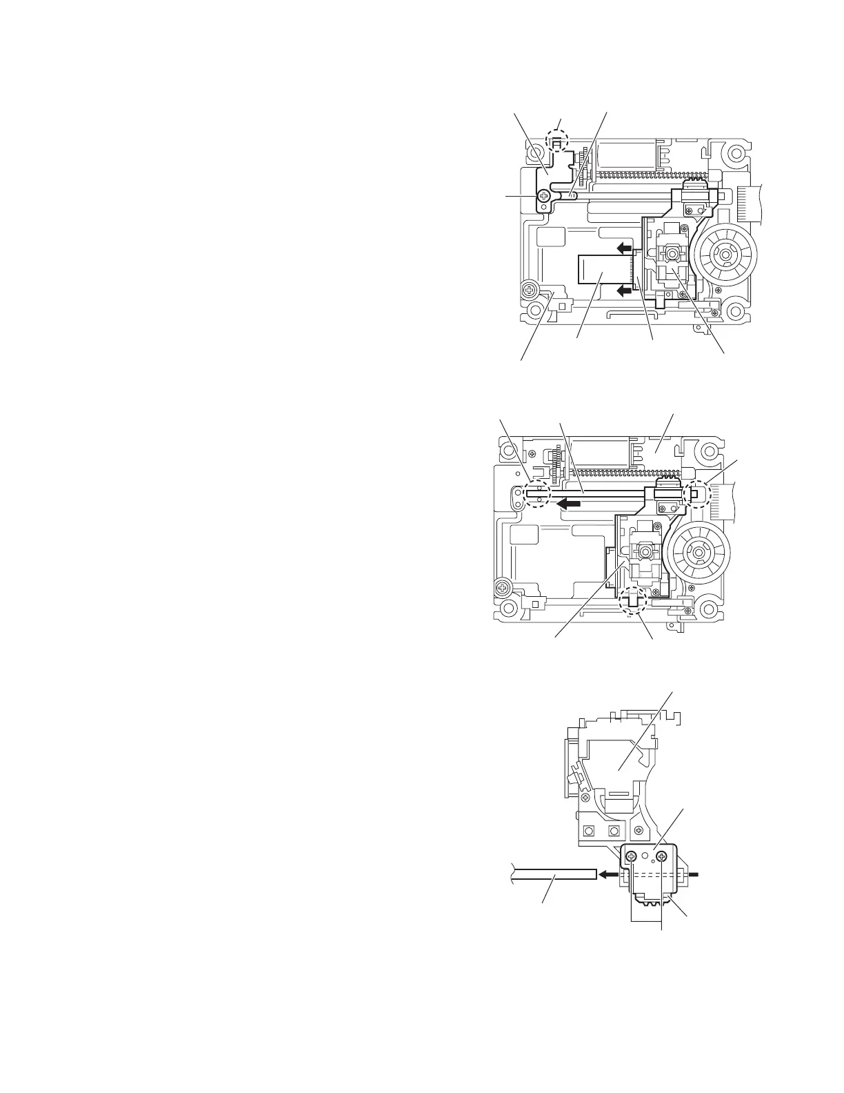
(3) Remove the screw D attaching the plate and thrust spring.
(See Fig.7.)
(4) Remove the engagement section g attaching the plate to
the feed holder and remove the plate with the thrust spring.
(See Fig.7.)
(5) Remove the shaft of the pickup from the section h on the
traverse mechanism assembly and remove the shaft from
the section i while moving it in the direction of the arrow.
(See Fig.8.)
(6) Remove the pickup from the section j of the traverse
mechanism assembly and take out the pickup with the
shaft. (See fig.8.)
(7) From the bottom side of the pickup, remove the two screws
E attaching the SW actuator and LEAD spring. (See
Fig.99.)
(8) Pull the shaft out of the pickup. (See Fig.9.)
Fig.7
Fig.8
Fig.9
Thrust spring
Pickup
Connector
Plate
Card wire
Feed holder
D
g
Shaft
Pickup
Traverse mechanism assembly
h
i
j
Pickup
SW actuator
LEAD spring
E
Shaft

 Loading...