1-20 (No.MB150)
3.2.5 Attaching the pickup
(See Figs.5,7 to 10)
• See "3.2.4 Removing the pickup".
(1) Attach the shaft, SW actuator and LEAD spring to the
pickup. (See Fig.9.)
(2) Align the pickup to the section j of the traverse mechanism
assembly first, and set the both ends of the shaft of the
pickup in the sections g and i of the traverse mechanism
assembly. (See Fig.8.)
(3) Attach the plate and thrust spring. (See Fig.7.)
(4) Remove solders from the short land sections c after
connecting the card wire to the connector on the pickup.
(See Figs.5 and 7.)
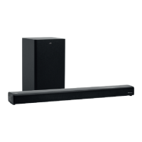
(5) Turn the feed gear M in the direction of the arrow 1 to move
the pickup in the direction of the arrow 2. (See Fig.10.)
Fig.10
3.2.6 Removing the feed motor
(See Figs.7,11 and 12)
• Remove the traverse mechanism assembly.
(1) From the top side of the traverse mechanism assembly,
remove the screw D attaching the plate and thrust spring.
(See Fig.7.)
(2) Remove the engagement section g attaching the plate to
the feed holder and remove the plate with the thrust spring.
(See Fig.7.)
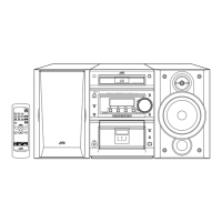
(3) Remove the wires from the soldered section k on the
spindle motor board. (See Fig.11.)
Reference:
When attaching the feed motor, pass the wire through
the section m on the spindle base. (See Fig.11.)
(4) Remove the feed holder, feed motor, lead screw, feed gear
E and feed gear M at the same time after removing the two
screws F attaching the feed holder. (See Fig.11.)
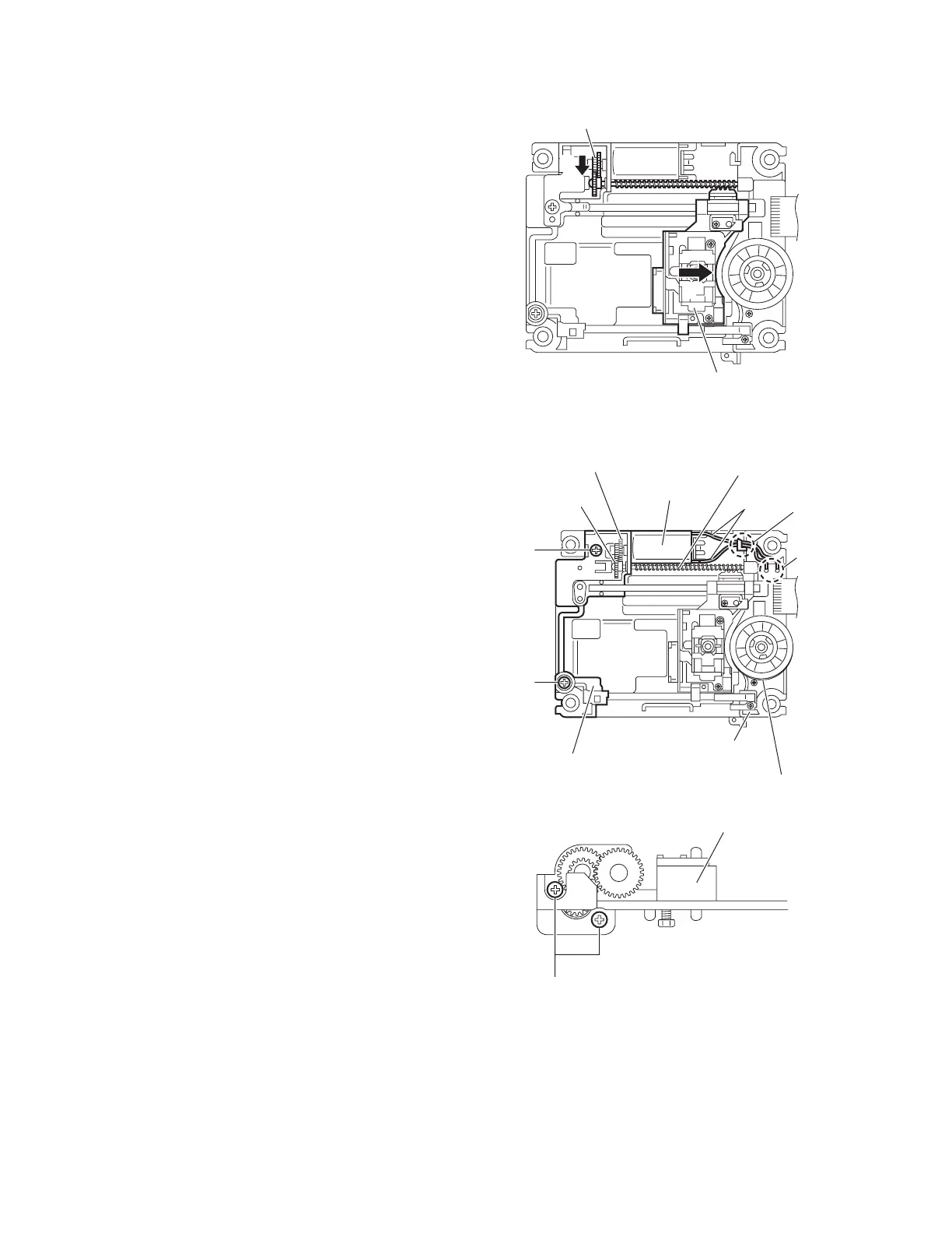
(5) From the side of the feed holder, remove the two screws G
attaching the feed motor. (See Fig.12.)
Fig.11
Fig.12
Feed gear M
Pickup
1
2
Spindle motor board
Spindle base
Feed holder
Feed gear E
Feed gear M
Feed motor
Lead screw
Wires
F
F
m
k
Feed holder
G

 Loading...