(No.MB487)1-29
3.3.7 Removing the feed motor
(See Figs.7 and 11)
• Remove the clamper base and traverse mechanism assembly.
(1) From the top side of the traverse mechanism assembly, re-
move the screw E and remove the feed bracket from the
section e. (See Fig.7.)
(2) Remove the guide shaft adj. spring from the claw f in the
direction of the arrow and remove the guide shaft adj.
spring. (See Fig.7.)
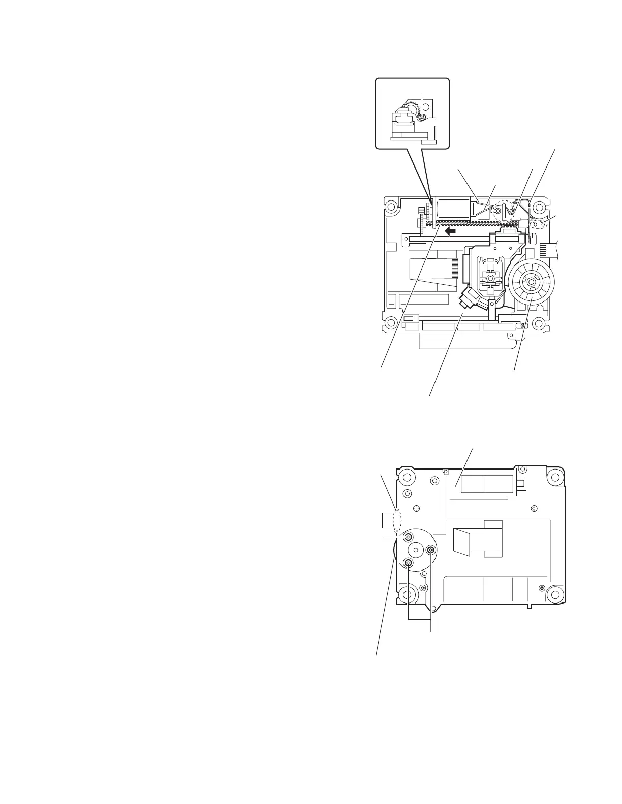
(3) Remove the wires (yellow and white) from the soldered
section k on the spindle motor board. (See Fig.11.)
Reference:
• When attaching the feed motor, pass the wires through
the section m on the spindle base. (See Fig.11.)
• Pass the wires through the lower section of the rod
spring. (See Fig.11.)
(4) Remove the screw shaft in the direction of the arrow. (See
Fig.11.)
(5) From the side of the traverse mechanism assembly, re-
move the screw G attaching the feed motor. (See Fig.11.)
(6) Take out the feed motor. (See Fig.11.)
3.3.8 Removing the spindle motor board
(See Figs.11 and 12)
• Remove the clamper base, traverse mechanism assembly and
DVD module board.
(1) From the top side of the traverse mechanism assembly, re-
move the wires (yellow and white) from the soldered sec-
tion k on the spindle motor board. (See Fig.11.)
(2) From the bottom side of the traverse mechanism assem-
bly, remove the three screws H attaching the spindle motor
board. (See Fig.12.)
Reference:
• When attaching the spindle motor board, pass the card wire
through the section n on the traverse mechanism assembly.
(See Fig.12.)
• When attaching the screws H, apply a locking agent them.
(See Fig.12.)
Fig.11
Fig.12
Spindle motor board
Screw shaft
Wire (white)
m
k
Traverse mechanism assembly
Wire (yellow)
Rod spring
G
Traverse mechanism assembly
H
n
H
Spindle motor board

 Loading...