2-3
2.3 DISASSEMBLY/ASSEMBLY OF MECHANISM
ASSEMBLY
2.3.1 General statement
The mechanism should generally be disassembled/assem-
bled in the EJECT mode (ASSEMBLY mode). (Refer to Fig.
2-3-1.)
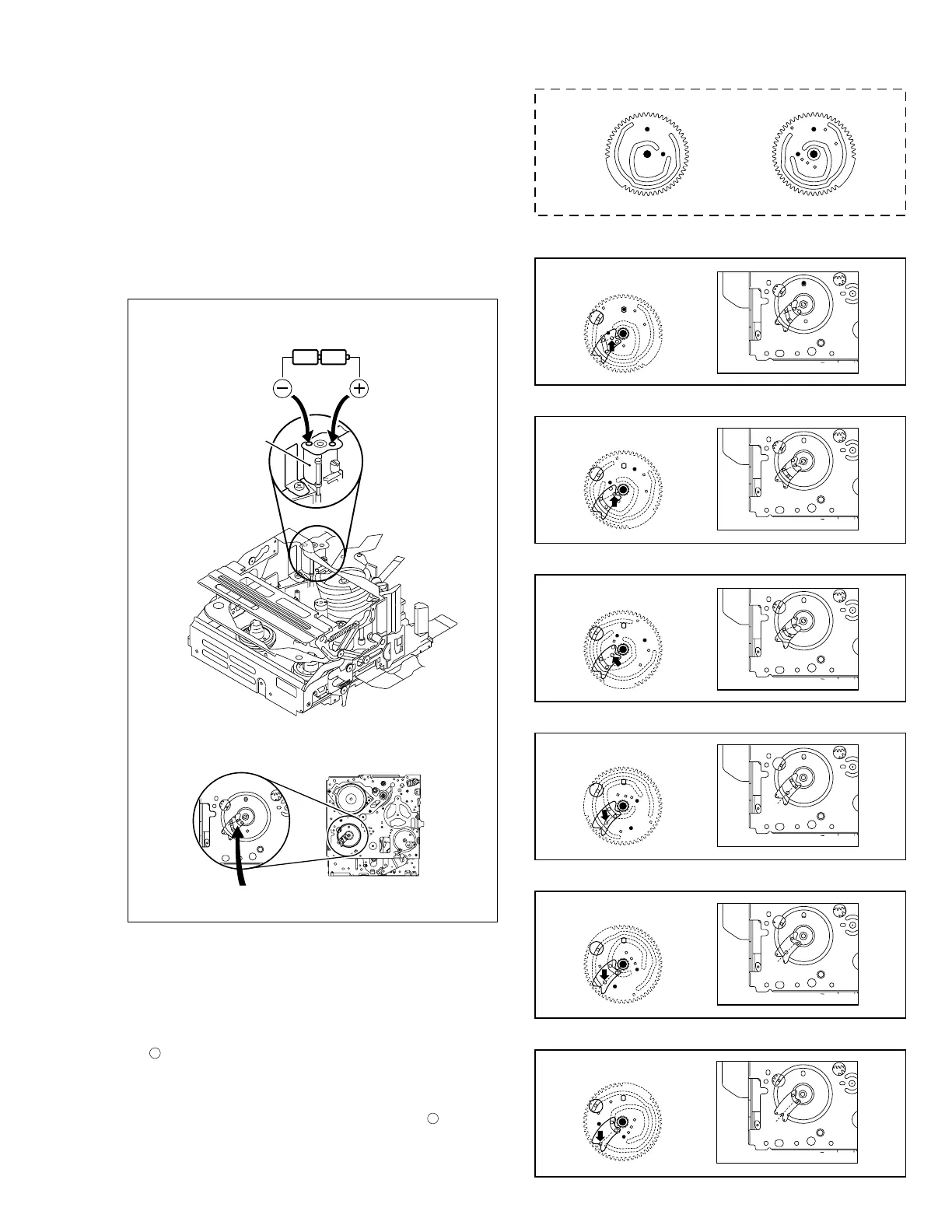
However, when the mechanism is removed from the main
body, it is set in the STOP mode. Therefore, after the
mechanism is removed from the main body, supply 3 V DC
to the electrode on the top of the loading motor to enter
the mechanism mode into the EJECT mode compulsory.
<Mechanism assembly/Cassette housing assembly>
<Back side of the mechanism assembly>
Fig. 2-3-1
Fig. 2-3-3
Fig. 2-3-4
Fig. 2-3-5
Fig. 2-3-6
Fig. 2-3-7
Motor
DC3V
EJECT mode
Back side of deck
<C IN mode>
<EJECT mode>
<STOP mode>
<SHORT FF mode>
<PLAY mode>
<REV mode>
<SUB CAM GEAR>
TOP VIEW BOTTOM VIEW
Fig. 2-3-8
2.3.2 Explanation of mechanism mode
The mechanism mode of this model is classified into six
modes as shown in Table 2-3-1. Each mechanism mode
can be distinguished from others by the relative position
of “
” mark on the sub cam gear to the inner or outer pro-
trusion on the main deck.
Refer to Fig. 2-3-2 to 2-3-8 below.
The EJECT mode, C IN mode and SHORT FF mode should
be recognized by the relative position of the “
” mark to
the inner protrusion, while the STOP mode, REV mode and
PLAY mode should be recognized by that to the outer pro-
trusion.
Fig. 2-3-2
 Loading...